Preparation method of grating with continuously changing diffraction efficiency

A diffraction efficiency and grating technology, applied in the field of waveguide optical diffraction elements, can solve problems such as poor uniformity of the outgoing beam

Active Publication Date: 2020-11-03
ZHEJIANG UNIV
View PDF24 Cites 2 Cited by
  • Summary
  • Abstract
  • Description
  • Claims
  • Application Information

AI Technical Summary

Problems solved by technology

[0007] The purpose of the present invention is to provide a method for preparing a grating with continuously changing diffraction efficiency, which can solve the disadvantage of poor uniformity of the outgoing beam of the optical system based on the waveguide grating coupler, and the preparation method is simple

Method used


Image

  • Preparation method of grating with continuously changing diffraction efficiency
  • Preparation method of grating with continuously changing diffraction efficiency
  • Preparation method of grating with continuously changing diffraction efficiency

Examples


Embodiment 1

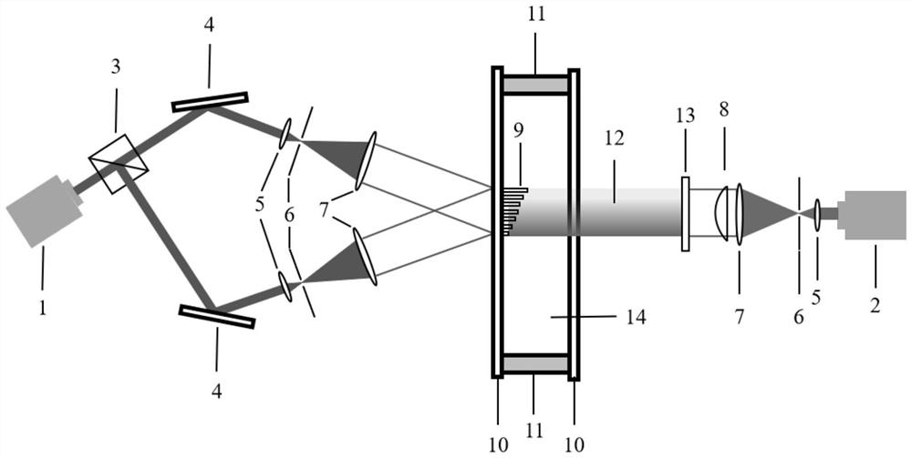
[0039] Such as figure 1 with Figure 7 As shown, after the light of wavelength a is emitted by the laser 1, it is split into two beams through the beam splitter 3. The two beams are reflected by the reflector 4 and form a certain angle, and then pass through the beam expander lens 5, The filter pinhole 6 and the collimating lens 7 interfere with each other after beam expansion, filtering and collimation.

[0040] After the light of wavelength b is emitted by the laser 2, it passes through the beam expander lens 5, the filter pinhole 6 and the collimator lens 7, after beam expansion, filtering and collimation, the light intensity of the obtained expanded beam has a Gaussian distribution. In order to obtain a light beam with uniform light intensity, it should go through the shaping lens 8 to make its light intensity uniform. After the light beam with the uniformly distributed light intensity of the wavelength b is superimposed on the neutral filter 13 of the continuously variable t...

Embodiment 2

[0052] Such as Figure 4 with Figure 7 As shown, after the light of wavelength a is emitted by the laser 1, it is split into two beams through the beam splitter 3. The two beams are reflected by the reflector 4 and form a certain angle, and then pass through the beam expander lens 5, The filter pinhole 6 and the collimating lens 7 interfere with each other after beam expansion, filtering and collimation.

[0053] After the light of wavelength b is emitted by the laser 2, it passes through the beam expander lens 5, the filter pinhole 6 and the collimator lens 7, after beam expansion, filtering and collimation, the light intensity of the obtained expanded beam has a Gaussian distribution. In order to obtain a light beam with uniform light intensity, it should go through the shaping lens 8 to make its light intensity uniform. After the light beam with the uniformly distributed light intensity of the wavelength b is superimposed on the neutral filter 13 of continuously changing tran...

Embodiment 3

[0071] Such as Picture 8 As shown, after the light of wavelength a is emitted by the laser 1, it passes through the beam expander lens 5, the filter pinhole 6 and the collimator lens 7 for beam expansion, filtering and collimation, and then passes through the wedge plate 15 and occurs behind the wedge plate. Interference of equal thickness.

[0072] After the light of wavelength b is emitted by the laser 2, it passes through the beam expander lens 5, the filter pinhole 6 and the collimator lens 7, after beam expansion, filtering and collimation, the light intensity of the obtained expanded beam has a Gaussian distribution. In order to obtain a light beam with uniform light intensity, it should go through the shaping lens 8 to make its light intensity uniform. After the light beam with the uniformly distributed light intensity of the wavelength b is superimposed on the neutral filter 13 of continuously changing transmittance, the light 12 with the continuous light intensity chang...


PUM


Abstract

The invention discloses a preparation method of a grating with continuously changing diffraction efficiency, which comprises the following steps of: adopting a first beam of light and a second beam oflight of which spectral bands are not overlapped with each other, forming interference light after the first beam of light is interfered, and forming light with continuous light intensity change in space by the second beam of light; irradiating interference light and light with continuous light intensity change in space to the photosensitive material at the same time, and obtaining a grating withcontinuously-changed diffraction efficiency; wherein the light-sensitive material is a light-cured material, the light-sensitive material is cured by interference light, and the light-inhibited light-sensitive material with continuous light intensity change in space is cured; or the photosensitive material is a material with photoinduced refractive index change. The preparation method provided bythe invention is obtained by directly exposing the photosensitive material, and mainly aims at the defect of poor uniformity of the emergent light beams of the existing optical system based on the waveguide grating coupler, so that the emergent light beams with uniformly distributed light intensity can be obtained; therefore, the imaging capability, the information transmission capability and other performances of the optical system are effectively improved.

Description

Technical field [0001] The invention relates to the field of waveguide optical diffractive elements, in particular to a method for preparing a grating with continuously changing diffraction efficiency. [0002] technical background [0003] Grating refers to a diffractive element with periodic changes in optical parameters (such as transmittance, refractive index, etc.) or spatial structure distribution. The preparation of grating is an important part of grating research. The optical materials selected include the following categories: glass material system, semiconductor material system, inorganic crystal material system, organic material system, etc. The preparation of gratings is researched around the process of these materials. Gratings can be divided into surface etched gratings and volume gratings. At present, surface-etched gratings modulate light beams through periodic spatial microstructures on the surface, mainly prepared by using photoresist grating masks, ion etching ...

Claims


Application Information

Patent Timeline
Patent Type & Authority Applications(China)
IPC IPC(8): G02B5/18G02B6/10
CPCG02B5/1814G02B5/1842G02B5/1857G02B6/10
Inventor 李海峰罗豪
Owner ZHEJIANG UNIV
Why Eureka
Try Eureka