

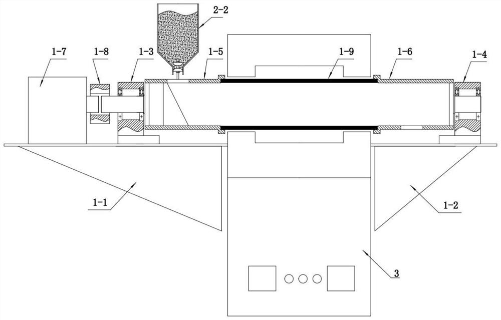
Device and method used for continuous material thermal treatment
A feeding device and material technology, applied in the direction of conveyor objects, loading/unloading, transportation and packaging, etc., can solve the problems of easily damaged furnace tubes and unsatisfactory heat treatment of small batch materials, so as to reduce production costs and improve heat treatment uniformity , the effect of increasing friction
- Summary
- Abstract
- Description
- Claims
- Application Information
AI Technical Summary
Problems solved by technology
Method used
Image

Examples
Embodiment 1
[0050] A method for continuous heat treatment of materials, the steps are as follows:
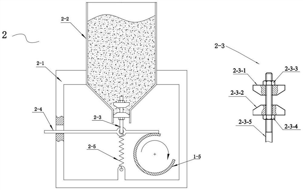
[0051] (1) Install the rotary device and the feeding device, adjust the distance between the two adjustment blocks on the blanking adjustment module to 9mm, pour the silicon nitride powder into the collection barrel, and adjust the furnace body so that the angle between the rotary device and the horizontal plane is 0.5 Spend.
[0052] (2) Raise the temperature of the tube furnace to 1250°C and keep it at a constant temperature, start the deceleration motor, and control its speed at 1.0r / min;
[0053] (3) Put the material guide plate of the feeding device on the feeding port of the left support cylinder, the feeding device starts to work, and the silicon nitride powder continuously enters the rotary device.
[0054] According to calculations, after the silicon nitride powder enters the left support cylinder from the feed port, it takes about 184 minutes to be discharged from the discharge p...
Embodiment 2
[0057] A method for continuous heat treatment of materials, the steps are as follows:
[0058] (1) Install the rotary device and the feeding device, adjust the distance between the two adjustment blocks on the feeding adjustment module to 11mm, pour the silicon nitride powder into the collection barrel, and adjust the furnace body so that the angle between the rotary device and the horizontal plane is 1.0 Spend.
[0059] (2) Raise the temperature of the tube furnace to 1250°C and keep it at a constant temperature, start the deceleration motor, and control its speed at 1.0r / min;
[0060] (3) Put the material guide plate of the feeding device on the feeding port of the left support cylinder, the feeding device starts to work, and the silicon nitride powder continuously enters the rotary device.
[0061] According to calculations, after the silicon nitride powder enters the left support cylinder from the feed port, it will be discharged from the discharge port after about 107 mi...
Embodiment 3
[0064] A method for continuous heat treatment of materials, the steps are as follows:
[0065] (1) Install the rotary device and the feeding device, adjust the distance between the two adjustment blocks on the feeding adjustment module to 11mm, pour the silicon nitride powder into the collection barrel, and adjust the furnace body so that the angle between the rotary device and the horizontal plane is 1.0 Spend.
[0066] (2) Heat the tube furnace to 1250°C and keep it at a constant temperature, start the geared motor, and control its speed at 2.0r / min;
[0067] (3) Put the material guide plate of the feeding device on the feeding port of the left support cylinder, the feeding device starts to work, and the silicon nitride powder continuously enters the rotary device.
[0068] According to calculations, after the silicon nitride powder enters the left support cylinder from the feed port, it is discharged from the discharge port after about 54 minutes. As shown in Table 1, ass...
PUM
 Abstract
Description
Claims
Application Information