

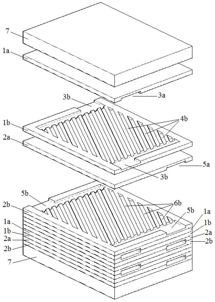
High-pressure-resistant reinforced heat transfer element adopting staggered channel structure and manufacturing method of high-pressure-resistant reinforced heat transfer element
A technology to strengthen heat transfer and channel structure, applied in the direction of laminated elements, indirect heat exchangers, heat exchanger types, etc. The problems of low thermal efficiency and high metal consumption of the heater achieve the effect of compact structure, high compactness and large heat transfer coefficient
- Summary
- Abstract
- Description
- Claims
- Application Information
AI Technical Summary
Problems solved by technology
Method used
Image

Examples
Embodiment
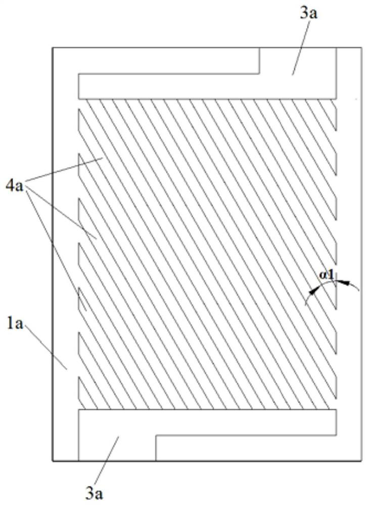
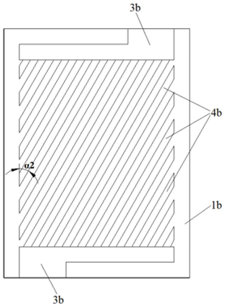
[0078] Cut the 3mm thick 304 stainless steel sheet into 24 pieces of 300mm×180mm, cut the 12mm thick 304 stainless steel plate into 2 pieces of 300mm×180mm; use WP-760 cleaning agent to clean the cut 26 pieces Clean the surface of the blank; use photolithographic anti-corrosion technology to transfer the structure designed in 1a drawing to the lower surface of 6 thin plates, transfer the structure designed in 1b drawing to the upper surface of 6 thin plates, and transfer the structure designed in 2a drawing to 6 transfer the structure designed in drawing 2b to the upper surfaces of 6 thin plates to form a specific structural anti-corrosion layer, and make anti-corrosion layers on the other surfaces of the metal plates that do not need to be etched. The main components of the anti-corrosion layer are Pentaerythritol triacrylate polymer; 100 g of FeCl 3 The crystal is dissolved in 300 ml of concentrated hydrochloric acid, and then diluted with 1200 ml of water to obtain the ferr...
PUM
 Abstract
Description
Claims
Application Information