Simultaneous reaction and separation of chemicals

A reactor, gas-phase reaction technology, applied in chemical instruments and methods, chemical/physical processes, inorganic chemistry, etc., can solve problems such as low methane conversion rate

Pending Publication Date: 2020-11-13
RGT UNIV OF CALIFORNIA
View PDF22 Cites 6 Cited by
  • Summary
  • Abstract
  • Description
  • Claims
  • Application Information

AI Technical Summary

Problems solved by technology

Reaction CH 4 ←→2H 2 +C is limited by equilibrium such that methane conversion is relatively low

Method used


Image

  • Simultaneous reaction and separation of chemicals
  • Simultaneous reaction and separation of chemicals
  • Simultaneous reaction and separation of chemicals

Examples


Embodiment 1

[0121] In a first example, methane is generated according to the simplified schematic Figure 16 into hydrogen and carbon in a reactor configuration. Methane was bubbled together with argon 1601 into molten metal alloy 1603 at 1065°C consisting of Ni / Bi in a molar ratio of 0.27:0.73, generating hydrogen and carbon. Referring to Table 1, when catalytic molten metal was used, almost complete conversion to hydrogen with high selectivity to hydrogen demonstrated the successful application of molten metal in methane pyrolysis.

[0122] The melt was prepared as follows: Solid bismuth and nickel were mixed in a Ni / Bi molar ratio of 0.27:0.73 in a 3 cm x 1.2 m stainless steel tube closed at one end with a weld cap. The reactor was mounted in a 4 cm alumina sleeve surrounded by four 30.5 cm 850 watt ceramic heaters surrounded by ceramic insulation. The space between the alumina tube and the stainless steel reactor is purged with nitrogen to prevent the stainless steel from scaling du...

Embodiment 2

[0127] In a second example, methane is generated according to the simplified schematic Figure 16 into hydrogen and carbon, among other products, in a reactor configuration. The reactor was placed so that the temperature of the headspace was lower than that of the melt. Methane was bubbled together with argon 1601) through a tube 1602 inserted into a molten metal alloy 1603 consisting of nickel / bismuth at 1050°C in a molar ratio of 0.27:0.73 in the first run, and in the second run The molten metal alloy 1603 in the test consisted of pure bismuth at 1050°C. The bubble column reactor was constructed of quartz and connected to a mass spectrometer to analyze the products 1605. The molten metal tower 1604 has a height of 150 mm and a diameter of 12 mm. A 3 mm quartz tube down into the liquid metal 1602 was used to introduce the gas into the melt. With the Swagelok UltraTorr Tube Fitting, the depth of the tube can be controlled to any height. All liquids are heated with an 850 ...

Embodiment 3

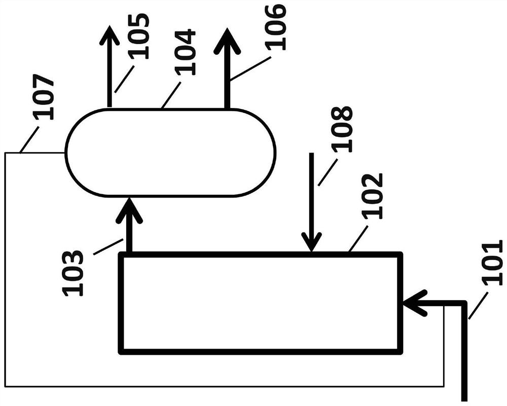
[0132] In a third embodiment, methane is Figure 10 into hydrogen and carbon in a reactor configuration. At position 1002, methane was bubbled with argon into a molten metal alloy at 1050°C consisting of Ni / Bi in a molar ratio of 0.27:0.73, and hydrogen and carbon were produced. All unreacted methane leaves the reactor as a gas at position 1004 along with some hydrogen. Some carbon is deposited at location 1005 , some carbon dissolves into the melt 1003 and diffuses to a separate location and deposits at location 1006 . In addition, some hydrogen dissolves and diffuses in the melt and exits the reactor at 1007, separated from unreacted methane.

[0133] The methane conversion and hydrogen yield from outlet gas stream 1004 for this experiment are shown in Table 3 below. During the pyrolysis in this example, methane conversion was observed to remain stable for 170 hours, supporting the conclusion that the solid carbon formed moves to the surface of the molten metal, thereby p...


PUM

PropertyMeasurementUnit
Outer diameteraaaaaaaaaa
The inside diameter ofaaaaaaaaaa
Outer diameteraaaaaaaaaa

Abstract

The reaction rate of hydrocarbon pyrolysis can be increased to produce solid carbon and hydrogen by the use of molten materials which have catalytic functionality to increase the rate of reaction andphysical properties that facilitate the formation and contamination-free separation of the solid carbon. Processes, materials, reactor configurations, and conditions are disclosed whereby methane andother hydrocarbons can be decomposed at high reaction rates into hydrogen gas and carbon products without any carbon oxides in a single reaction step. The process also makes use of specific propertiesof selected materials with unique solubilities and/or wettability of products into (and/or by) the molten phase to facilitate generation of purified products and increased conversion in more generalreactions.

Description

[0001] Cross References to Related Applications [0002] This application is co-pending and commonly assigned U.S. Provisional Application No. 62 / 586,943, filed November 16, 2017, entitled "Simultaneous Reaction and Separation of Chemical Substances" pursuant to 35 U.S.C. § 119(e) Priority and benefit of the said US provisional application is hereby incorporated by reference in its entirety. [0003] Statement of Federally Sponsored Research or Development [0004] This invention was made with government support under Grant Nos. DE-FG02-89ER14048 awarded by the U.S. Department of Energy and Grant Nos. CNS-0960316 and DMR-1121053 awarded by the National Science Foundation. The government has certain rights in this invention. technical field [0005] The present disclosure relates to the production of hydrogen and solid carbon from methane. The disclosure also relates to the production of hydrogen and solid carbon from other hydrocarbon feedstocks, including natural gas, p...

Claims


Application Information

Patent Timeline
IPC IPC(8): B01J8/04
CPCB01J8/067B01J8/226B01J8/228B01J10/005B01J8/0045B01J8/0055B01J8/006B01J8/007B01J8/009B01J8/025B01J2208/00141B01J2208/00761C01B3/26B01J23/6447B01J23/835B01J23/62B01J23/8437B01J23/626B01J23/825B01J27/0576B01J35/12B01J2208/00203B01J8/06B01J8/0278B01J27/08B01J35/0006C01B2203/0277C01B2203/1011C01B2203/1058C01B2203/1241
Inventor 埃里克·W·麦克法兰奇斯·乌普汉曾济人克拉克·帕默苏士钊戴维德·曼尼尼姜道亨纳扎宁·拉希米霍里亚·梅蒂乌迈克尔·戈登
Owner RGT UNIV OF CALIFORNIA
Why Eureka
Try Eureka