Grinding device for small-diameter optical lens

An optical lens and small-diameter technology, which is applied in the mechanical field, can solve the problems of slow production efficiency, broken corners of the lens, and inconvenient grinding of edges and corners, and achieve the effect of easy removal, avoiding reprocessing, and saving procedures

Inactive Publication Date: 2020-11-20
付小毛
View PDF1 Cites 4 Cited by
  • Summary
  • Abstract
  • Description
  • Claims
  • Application Information

AI Technical Summary

Problems solved by technology

[0004] When the traditional lens edger grinds the corners of the lens, it clamps the two ends of the lens, uses the grinding wheel to grind slowly, and then performs chamfering, resulting in slow production efficiency, and because the lens material is relatively Brittle, it is easy to damage the corners of the lens when clamping the two ends, making it difficult to control the precision and quality of the lens. The matching concave and convex clamping blocks are set to clamp the upper and lower sides of the lens for grinding and chamfering, which makes the production efficie

Method used


Image

  • Grinding device for small-diameter optical lens
  • Grinding device for small-diameter optical lens
  • Grinding device for small-diameter optical lens

Examples


Embodiment 2

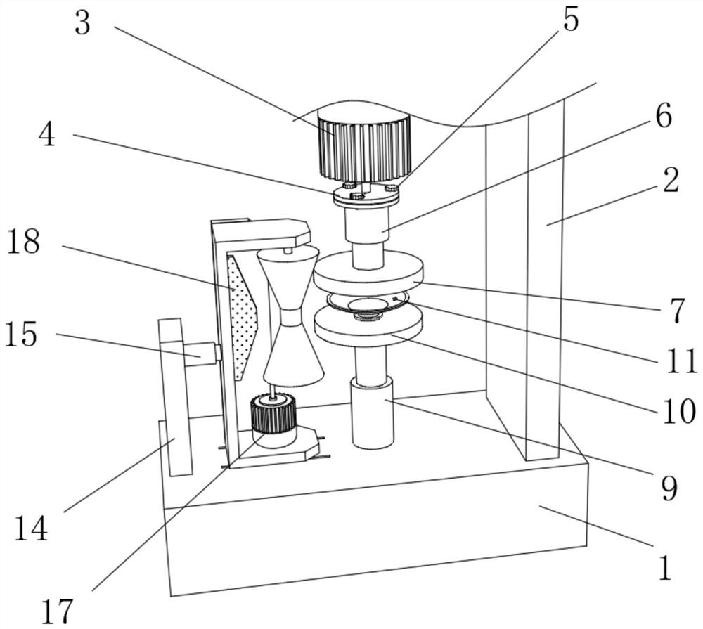
[0041] refer to Figure 4-5 , a grinding device for small-diameter optical lenses. Compared with Embodiment 1, in this embodiment, a through hole 28 is provided at the center of the inner bottom end of the suction cup seat 19 and the rubber layer 20, and the lower end of the suction cup seat 19 is fixedly connected with a rectangular The sealing tube 21, the side end of the rectangular sealing tube 21 is provided with a second air hole 23, the upper end of the second clip 10 is rotatably connected with a fixed cylinder 29, and the side end of the fixed cylinder 29 is provided with a first air hole 22 matching the second air hole 23, A tension spring 24 is fixedly connected between the lower end of the rectangular sealing tube 21 and the inner bottom end of the fixed tube 29, a pair of T-shaped limit sliders 25 are integrated at the side end of the rectangular sealing tube 21, and a pair of T-shaped limit sliders 25 are arranged on the inner wall of the fixed tube 29. Type limi...


PUM


Abstract

The invention belongs to the technical field of machinery, particularly relates to a grinding device for a small-diameter optical lens. The grinding device aims at solving the problem that in the prior art, a lens and a rubber layer are difficult to take down after being tightly extruded due to the structure of the grinding device for the optical lens for fixing the lens. According to the technical scheme, the grinding device comprises a fixing base with the upper end fixedly connected with an L-shaped fixing seat; a lens fixing mechanism comprises a first motor, a first electric push rod, a first clamping piece, a second clamping piece, a two-way suction cup and a second electric push rod; and the grinding assembly comprises a butterfly surface grinding rod. According to the grinding device for the small-diameter optical lens, the upper and lower edges of the optical lens can be formed through the arranged butterfly surface grinding rod, later reprocessing is avoided, and procedures are saved; through the arrangement of the two-way suction cup, the closed space formed between the rubber layer and the optical lens is freely opened and sealed, so that the suction force between the rubber layer and the optical lens is changed, and the optical lens is conveniently and stably placed and smoothly taken down.

Description

technical field [0001] The invention relates to the field of mechanical technology, in particular to a grinding device for small-diameter optical lenses. Background technique [0002] Optical glass is mixed with oxides of high-purity silicon, boron, sodium, potassium, zinc, lead, magnesium, calcium, barium, etc. according to a specific formula, melted at high temperature in a platinum crucible, stirred evenly with ultrasonic waves, and removed air bubbles; The temperature is lowered slowly over time to avoid internal stress in the glass block. The cooled glass blocks must be measured by optical instruments to check whether the purity, transparency, uniformity, refractive index and dispersion rate meet the specifications. Qualified glass blocks are heated and forged to form optical lens blanks. [0003] Optical lenses are mostly used in optical equipment such as glasses, lenses, photographic camera lenses, etc., and achieve different viewing effects by refracting light. In...

Claims


Application Information

Patent Timeline
IPC IPC(8): B24B13/00B24B13/005B24B9/14B24B41/06
CPCB24B9/14B24B9/146B24B13/00B24B13/0055
Inventor 付小毛
Owner 付小毛
Why Eureka
Try Eureka