Device and method for controlling growth state of carbon nano tubes based on decoupling heat treatment and application thereof

A technology of carbon nanotubes, growth state, applied in chemical instruments and methods, carbon compounds, inorganic chemistry, etc., can solve problems such as limitations

Inactive Publication Date: 2020-11-20
SHANDONG UNIV
View PDF7 Cites 0 Cited by
  • Summary
  • Abstract
  • Description
  • Claims
  • Application Information

AI Technical Summary

Problems solved by technology

Often in a typical chemical vapor deposition growth system, the catalyst particle formation temperature, gas phase carbon precursor decomposition temperature, and carbon nanotube growth temperature are inevitably coupled, thus limiting the ability to fully understand and accurately control the entire growth process

Method used


Image

  • Device and method for controlling growth state of carbon nano tubes based on decoupling heat treatment and application thereof
  • Device and method for controlling growth state of carbon nano tubes based on decoupling heat treatment and application thereof
  • Device and method for controlling growth state of carbon nano tubes based on decoupling heat treatment and application thereof

Examples


Embodiment 1

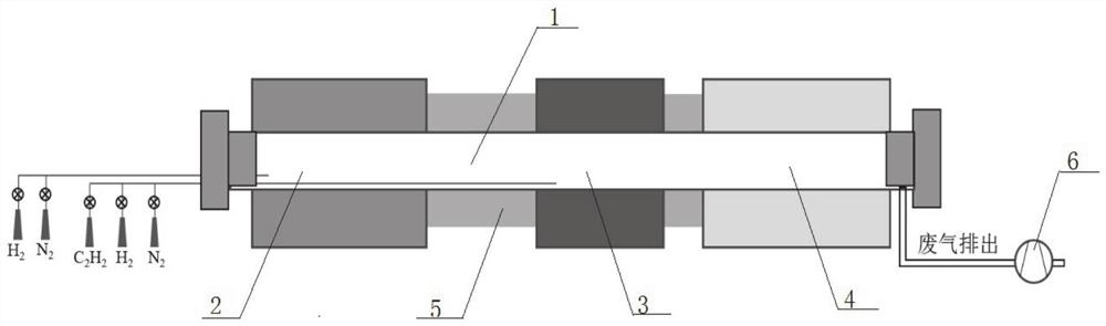
[0066] Step 1: Purging the experimental reactor with inert gas and maintaining an inert environment to eliminate the interference of the air environment on the experiment.

[0067] Step 2: After the carbon fiber is modified by electrochemical anodization, the carbon fiber is immersed in 0.05mol / L Co(NO 3 ) 2 Load the catalyst precursor in the ethanol solution for 10 minutes;

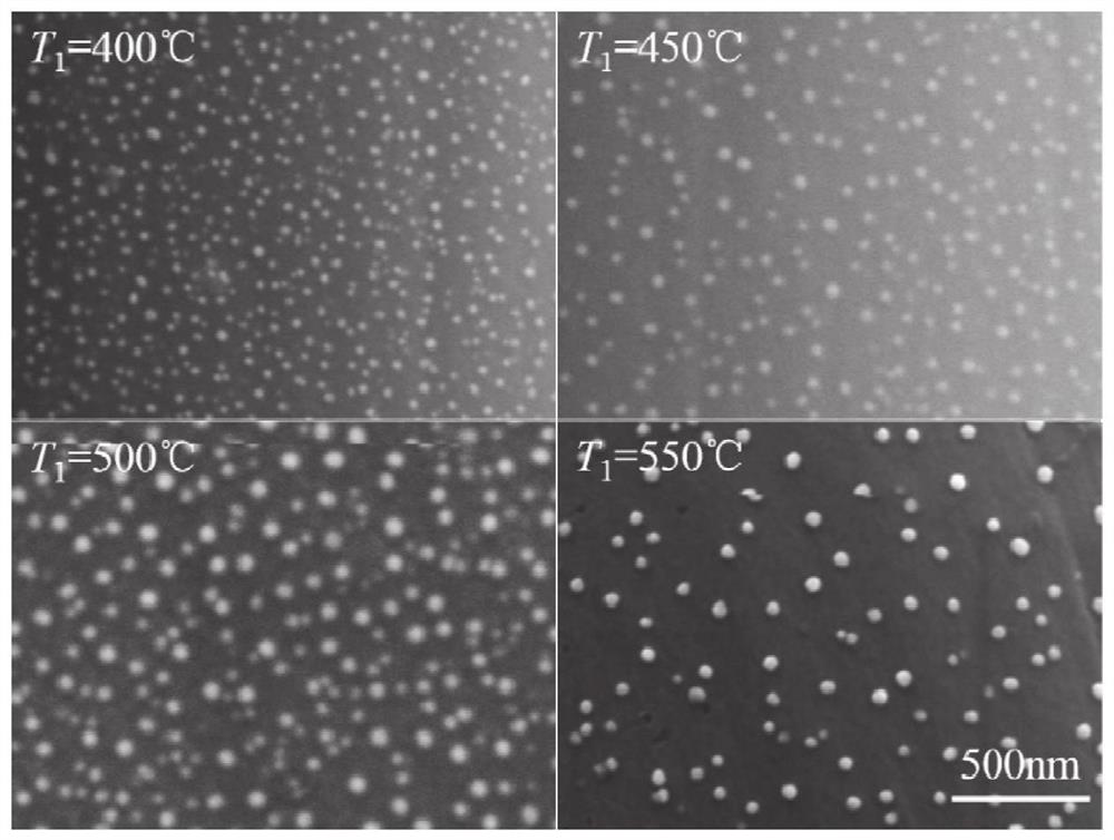
[0068] Step 3: Put the carbon fiber obtained in step 2 into the catalyst reduction unit of the reactor, under an inert gas atmosphere, use H 2 Reducing the catalyst precursor coating to metal nanoparticles, the reduction temperature is 400°C, and the reduction time is 15 minutes;

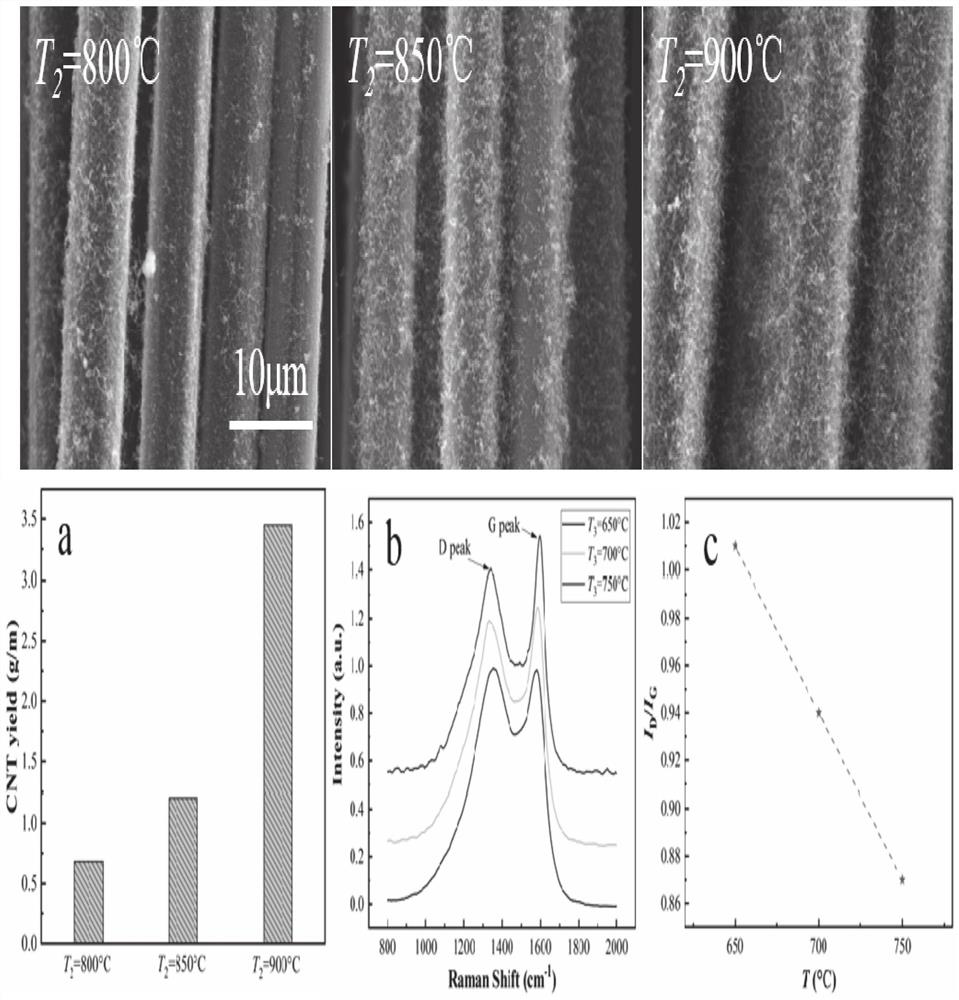
[0069] Step 4: Continue to extend the carbon fiber sample obtained in step 3 into the reactor, pass in the reaction gas, decompose in the carbon source decomposition unit at 800°C for 5 minutes, and then enter the carbon nanotube growth unit to synthesize carbon nanotubes at 650°C , and finally collect the samples.

[0070...

Embodiment 2

[0072] Step 1: Purging the experimental reactor with inert gas and maintaining an inert environment to eliminate the interference of the air environment on the experiment.

[0073] Step 2: After the carbon fiber is modified by electrochemical anodization, the carbon fiber is immersed in 0.05mol / L Co(NO 3 ) 2 Load the catalyst precursor in the ethanol solution for 10 minutes;

[0074] Step 3: Put the carbon fiber obtained in step 2 into the catalyst reduction unit of the reactor, under an inert gas atmosphere, use H 2 The catalyst precursor coating was reduced to metal nanoparticles, the reduction temperature was 450°C, and the reduction time was 15 minutes;

[0075] Step 4: Continue to extend the carbon fiber sample obtained in step 3 into the reactor, pass in the reaction gas, decompose in the carbon source decomposition unit at 800°C for 5 minutes, and then enter the carbon nanotube growth unit to synthesize carbon nanotubes at 650°C , and finally collect the samples.

...

Embodiment 3

[0078] Step 1: Purging the experimental reactor with inert gas and maintaining an inert environment to eliminate the interference of the air environment on the experiment.

[0079] Step 2: After the carbon fiber is modified by electrochemical anodization, the carbon fiber is immersed in 0.05mol / L Co(NO 3 ) 2 Load the catalyst precursor in the ethanol solution for 10 minutes;

[0080] Step 3: Put the carbon fiber obtained in step 2 into the catalyst reduction unit of the reactor, under an inert gas atmosphere, use H 2Reducing the catalyst precursor coating to metal nanoparticles, the reduction temperature is 500°C, and the reduction time is 15 minutes;

[0081] Step 4: Continue to extend the carbon fiber sample obtained in step 3 into the reactor, pass in the reaction gas, decompose in the carbon source decomposition unit at 800°C for 5 minutes, and then enter the carbon nanotube growth unit to synthesize carbon nanotubes at 650°C , and finally collect the samples.

[0082]...


PUM

PropertyMeasurementUnit
diameteraaaaaaaaaa
diameteraaaaaaaaaa
diameteraaaaaaaaaa

Abstract

The invention provides a device and method for controlling the growth state of carbon nano tubes based on decoupling heat treatment and application thereof, and belongs to the technical field of carbon nano tube preparation. By designing a multi-zone rapid thermal CVD reactor, the catalyst formation temperature (T1), the carbon source decomposition temperature (T2) and the carbon nano tube nucleation and growth temperature (T3) are completely decoupled. Based on the decoupling technology, each of the three temperatures (T1, T2 and T3) possibly influencing the growth of a carbon nano tube can be independently researched, so that the decoupling technology has a good practical application value.

Description

technical field [0001] The invention belongs to the technical field of carbon nanotube preparation, and in particular relates to a device and method for controlling the growth state of carbon nanotubes based on decoupling combined heat treatment and an application thereof. Background technique [0002] The information disclosed in this background section is only intended to increase the understanding of the general background of the present invention, and is not necessarily taken as an acknowledgment or any form of suggestion that the information constitutes the prior art already known to those skilled in the art. [0003] The synthesis of carbon nanotubes on the surface of carbon fibers by chemical vapor deposition involves the decomposition of carbon source gas and the subsequent self-assembly growth of graphitic carbon on the surface of catalyst particles. Precisely tuning the structural features (e.g., diameter, areal density) and mass of CNTs is critical for the commerc...

Claims


Application Information

Patent Timeline
Patent Type & Authority Applications(China)
IPC IPC(8): C01B32/162
CPCC01B32/162
Inventor 王成国秦建杰王延相魏化震陈刚王启芬姚志强马子明崔博文岳阳王永博
Owner SHANDONG UNIV
Why Eureka
Try Eureka