
Thermoelectric device performance testing device

A technology for thermoelectric devices and testing devices, applied in the direction of measuring devices, testing of machine/structural components, instruments, etc., can solve the problems of inability to test non-standard thermoelectric devices, and achieve the effect of complete functions

Inactive Publication Date: 2020-11-20
MATERIAL INST OF CHINA ACADEMY OF ENG PHYSICS
View PDF7 Cites 7 Cited by
  • Summary
  • Abstract
  • Description
  • Claims
  • Application Information

AI Technical Summary

Problems solved by technology

[0005] The purpose of the present invention is to provide a performance testing device for thermoelectric devices in view of the problem in the prior art that it is impossible to test non-standard thermoelectric devices with a wider size range

Method used


Image

  • Thermoelectric device performance testing device
  • Thermoelectric device performance testing device
  • Thermoelectric device performance testing device

Examples


Embodiment 1

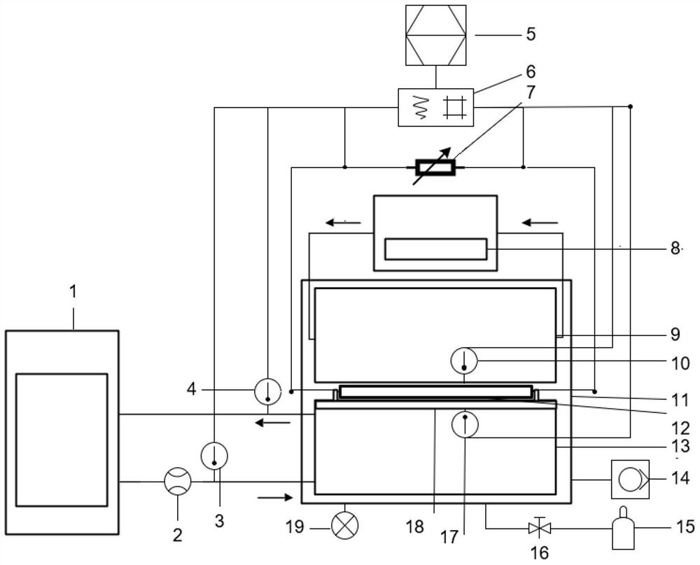
[0040] Such as figure 1 As shown, a device for performance testing of thermoelectric devices in a wide size range includes a test module, a data acquisition and processing module, an atmosphere control module and a data processing terminal 5 .

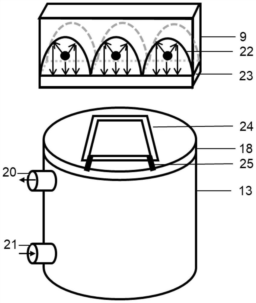
[0041] Such as figure 2As shown, the test module is used to test and collect thermoelectric performance data of the thermoelectric device 12 to be tested under different temperature differences and atmospheric conditions. The test module includes a test chamber 11 , a constant temperature circulator 1 , a flow rate control module 2 , an inlet temperature sensor 3 , an outlet temperature sensor 4 and a circulating water cooler 8 . The flow rate control module 2 adopts a mass flow controller. The test cavity 11 is a sealed cuboid structure, made of 304 stainless steel; the test cavity 11 is also provided with a heating platform 9 and a cooling platform 13, and the heating platform 9 is used to provide the temperature of the hot end of...

Embodiment 2

[0047] Such as Figure 4-Figure 5 As shown, the difference between this embodiment and Embodiment 1 is that the device for performance testing of thermoelectric devices in a wide range of sizes in this embodiment adopts a test platform (groove) 26, and uses an engraved groove 27 as a fixed groove to The thermoelectric device 12 is fixed in the middle, and is used to realize the test of the low-thickness test sample.

Embodiment 3

[0049] Such as Figure 6 As shown, the difference between this embodiment and Embodiment 2 is that the system device for performance testing of thermoelectric devices in a wide size range in this embodiment uses a liquid flow meter 28 and a ball valve 29 instead of a mass flow controller, that is, a flow rate control module 2 A liquid flow meter 28 and a ball valve 29 are used.


PUM


Abstract

The invention discloses a thermoelectric device performance testing device which comprises a heating platform, a refrigerating platform, a closed testing cavity and a vacuum pump. The method is designed based on a one-dimensional steady-state heat flow method. A to-be-tested thermoelectric device is arranged in a vacuum test cavity. An infrared radiation heating mode (the temperature of the hot end ranges from 20 DEG C to 600 DEG C) is adopted by the hot end; the size limitation of the thermoelectric device to be tested is reduced due to the liquid heat measurement mode (the temperature rangeof the cold end is-50 DEG C to 200 DEG C) of the cold end, and the output power and the conversion efficiency of the thermoelectric device with the wide size range (10mm to 100mm) can be accurately tested; a test can be carried out at the temperature of 0-650 DEG C under a variable temperature difference condition; moreover, the vacuum pump is used for pumping the test cavity into a vacuum cavityfor testing, so that the influence caused by heat convection is avoided. The method has great advantages in accurate testing of the performance of the non-standard thermoelectric device, repeatabilityand stability testing required by commercialization of the thermoelectric device can be achieved, and the method is high in applicability.

Description

technical field [0001] The invention relates to the technical field of functional materials and device testing, in particular to a thermoelectric device performance testing device. Background technique [0002] With the development of the times, the world today has higher and higher requirements for energy and the environment. Finding new energy or increasing its utilization efficiency on the original basis has become one of the focuses of governments and scientific researchers. Thermoelectric devices can directly convert electric heat by virtue of the Seebeck effect and Peltier effect, and have attracted extensive attention in waste heat power generation and mobile refrigeration. At present, research generally focuses on new materials, and there is still a lack of systematic work in the field of thermoelectric devices. The corresponding bottlenecks mainly lie in the irregularities of testing equipment and low conversion efficiency of materials. The thermoelectric device pe...

Claims


Application Information

Patent Timeline
IPC IPC(8): G01M99/00G01N25/20
CPCG01M99/00G01N25/20
Inventor 任广坤邓舜杰文明刘寅可郑哲邓立蔡金光陈俊光胡俊
Owner MATERIAL INST OF CHINA ACADEMY OF ENG PHYSICS
Learn More