
Neutral circuit arrangement

A technology of circuit device and neutral line, which is applied in the field of high-voltage direct current transmission system, can solve the problems of increasing cost and occupied area, and achieve the effects of reducing effective circuit inductance, increasing attenuation rate, and increasing effective circuit resistance

Active Publication Date: 2020-11-20
HITACHI ENERGY SWITZERLAND AG
View PDF4 Cites 0 Cited by
  • Summary
  • Abstract
  • Description
  • Claims
  • Application Information

AI Technical Summary

Problems solved by technology

May also require additional cooling, increasing cost and footprint

Method used


Image

  • Neutral circuit arrangement
  • Neutral circuit arrangement
  • Neutral circuit arrangement

Examples


Embodiment Construction

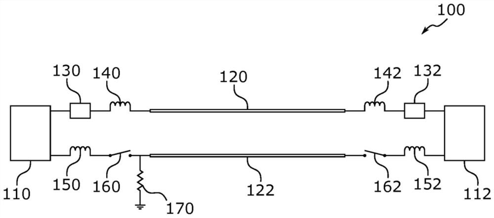
[0034] figure 1 A (conventional) HVDC power transmission system 100 is illustrated. The system 100 is set up in an asymmetric monopole configuration and includes a first VSC station 110 and a second VSC station 112 . One or both of VSC stations 110 and 112 may, for example, include one or more modular multilevel converters (MMCs). One or more of the MMCs may be, for example, a half-bridge MMC (HB-MMC).

[0035]The first VSC station 110 and the second VSC station 112 are connected via a DC link. The DC link includes a DC pole 120 and a DC neutral 122 . The first VSC station 110 is connected to the DC pole line 120 via a hybrid HVDC breaker (HHB) 130 and a current limiting reactor (CLR) 140 . The first VSC station 110 is connected to the DC neutral line 122 via a CLR 150 and a switching element 160 . Second VSC station 112 is connected to DC pole line 120 via HHB 132 and CLR 142 . Second VSC station 112 is connected to DC neutral 122 via CLR 152 and switching element 162 ....


PUM


Abstract

A circuit arrangement for decaying of a transient current flow between a first point and a second point on a neutral line of a high-voltage direct current (HVDC) power transmission system is provided.The circuit arrangement may include a first branch including a first winding and a resistive element connected in series, and a second branch including a second winding and a switching element connected in series. The first branch and the second branch may be connected in parallel between the first point and the second point. The first winding and the second winding may form part of separate inductors, or be mutually coupled and form part of a same mutual inductor. An inductance of the first winding may be smaller than an inductance of the second winding. A voltage source converter (VSC) station and a HVDC power transmission system are also provided, as well as methods for modifying / upgrading a HVDC power transmission system and methods for operating a circuit arrangement during a converter bus fault.

Description

technical field [0001] The present disclosure relates to the field of high voltage direct current (HVDC) power transmission systems including one or more voltage source converters (VSC). In particular, the present disclosure relates to the handling of fault currents on a direct current (DC) neutral wire of an HVDC power transmission system. Background technique [0002] As VSCs prove more proficient in control and performance, multi-terminal VSC DC grid configurations are on the rise. In a DC grid operation scenario it may be necessary that the current is within the rated capacity of the HHB when opening eg in a hybrid HVDC breaker (HHB). As a result, such a DC grid can be equipped with a current limiting reactor (CLR) connected in series with the HHB on the DC pole line and also on the DC neutral line. One or more CLRs may, for example, limit the fault current below the rated capacity of the corresponding HHB during, for example, a fault current interruption. [0003] Fo...

Claims


Application Information

Patent Timeline
Patent Type & Authority Applications(China)
IPC IPC(8): H02H3/32H02H3/34H02H7/12H02M1/32H02H9/00H02H9/02
CPCH02H7/1203H02H9/005H02H9/021Y02E60/60
Inventor V·坎南英·江-赫夫纳
Owner HITACHI ENERGY SWITZERLAND AG
Learn More