Part inner hole coating machining method and system, and device

A processing method and coating technology, which is applied in the coating process and coating of metal materials, can solve the problems of poor stability of the coating process, easy cracks, holes, and easy deformation of parts, so as to reduce the deformation or even cracking of parts. risk, prevent the coating of parts from falling off, and increase the effect of bonding strength

Pending Publication Date: 2020-11-24
天津辉锐激光科技有限公司
View PDF3 Cites 2 Cited by
  • Summary
  • Abstract
  • Description
  • Claims
  • Application Information

AI Technical Summary

Problems solved by technology

[0003] At present, the methods for preparing inner hole coatings of parts mainly include thermal spraying method and surfacing welding method, but due to the small operating space and high difficulty of operation in the inner hole, the stability of the coating process is poor, and cracks and holes are prone to appear. and other defects
Moreover, due to the low bonding force between the prepared coating and the surface layer of the part and the excessive thermal stress, the part is easily deformed, so that the qualified rate of the prepared part with the coating is low

Method used


Image

  • Part inner hole coating machining method and system, and device
  • Part inner hole coating machining method and system, and device
  • Part inner hole coating machining method and system, and device

Examples


Embodiment 1

[0056] In this embodiment, an additive manufacturing part (material: SUS306 stainless steel) is selected as the prefabricated part with a hole structure. The coating powder is made of Stellite 6 cobalt-based alloy. Such as Figure 6 Shown, the concrete implementation process of the present invention is as follows:

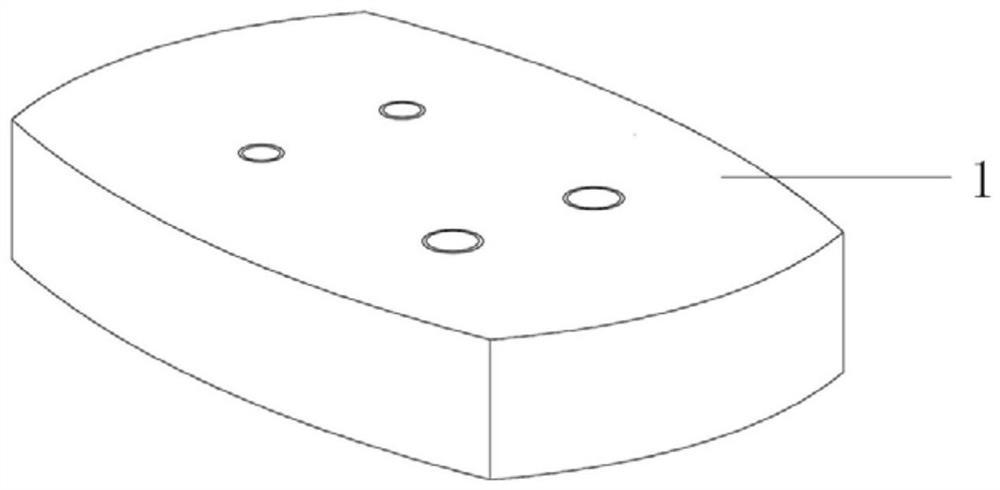
[0057] Step S1: providing a preform with a hole structure.

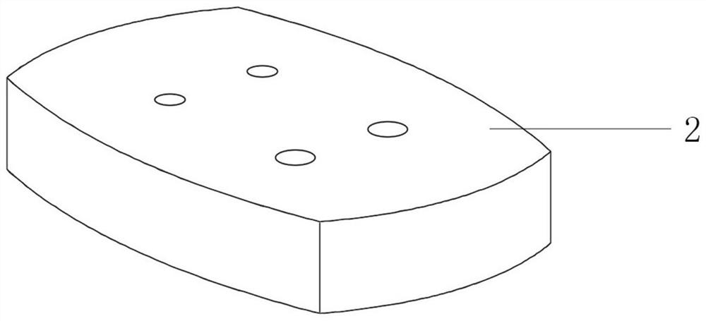
[0058]Step S2: Take the axis perpendicular to the plane where the hole structure is located passing through the center of the hole structure of the prefabricated part as the center line, and use a hand-held angle grinder to grind out a two-sided symmetrical conical structure at the position of the inner hole of the base material of the part, The diameter of the smallest part of the two-sided symmetrical opposite-top conical structure should not be smaller than the aperture of the prefabricated part with the hole structure.

[0059] Step S3: Use alcohol to remove the oil stain on the surface of the poli...

Embodiment 2

[0068] In this embodiment, an additive manufacturing part (material: SUS306 stainless steel) is selected as the prefabricated part with a hole structure. The coating powder is made of Stellite 6 cobalt-based alloy. Concrete implementation process of the present invention is as follows:

[0069] Step S1: providing a preform with a hole structure.

[0070] Step S2: Taking the axis perpendicular to the plane where the hole structure is located passing through the center of the hole structure of the prefabricated part as the center line, use a hand-held angle grinder to grind a single-sided conical structure at the position of the inner hole of the base material of the part. The diameter of the smallest part of the tapered structure should not be smaller than the hole diameter of the prefabricated part with the hole structure.

[0071] Step S3: Use alcohol to remove the oil stain on the surface of the polished preform with a pore structure, and use mechanical processing equipmen...


PUM

PropertyMeasurementUnit
diameteraaaaaaaaaa

Abstract

The invention discloses a part inner hole coating machining method and system, and a device, relates to the technical field of laser additive manufacturing, and is used for machining a coating in an inner hole of a part, so that the service life of the part can be prolonged. The part inner hole coating machining method comprises the following steps: providing a prefabricated part with a hole structure; according to the coating cladding strategy, controlling a laser cladding device to form the coating in the hole structure of the prefabricated part, so that a part blank is obtained, wherein thecoating cladding strategy is determined by the structural parameters of the hole structure; and controlling a heat treatment device to carry out heat treatment on the part blank. The terminal devicecomprises a processor and a communication interface, so that the part inner hole coating machining method can be realized. The part inner hole coating machining method provided by the invention is used for preparing the wear-resistant coating of the inner hole.

Description

technical field [0001] The invention relates to the technical field of laser additive manufacturing, in particular to a method, equipment and system for processing inner hole coating of parts. Background technique [0002] In engineering fields such as mining machinery, due to the harsh service environment and the repeated friction between the inner hole of the metal part and the tractor, parts are prone to wear and corrosion, which reduces the service life of the parts. In the prior art, the method of adding coating is often used to modify the surface of the inner hole of the part, but because the processing space of the inner hole is not open, it is difficult to process and repair the inner hole of the part. [0003] At present, the methods for preparing inner hole coatings of parts mainly include thermal spraying method and surfacing welding method, but due to the small operating space and high difficulty of operation in the inner hole, the stability of the coating proces...

Claims


Application Information

Patent Timeline
Patent Type & Authority Applications(China)
IPC IPC(8): C23C24/10C22F1/10
CPCC23C24/103C22F1/10
Inventor 周崇李冬杰齐欢
Owner 天津辉锐激光科技有限公司
Why Eureka
Try Eureka