High-precision rapid measurement device and method for engine blade tip gap

A technology of blade tip clearance and measuring device, which is applied in the direction of measuring device, optical device, instrument, etc., and can solve the requirements of radio frequency circuit design, processing and engineering application, such as relatively high requirements for large size and unfavorable installation, and casing conductivity requirements, etc. problem, to achieve the effect of simple and efficient signal processing method, improved measurement resolution, and simple and efficient signal demodulation algorithm

Active Publication Date: 2020-11-24
BEIJING CHANGCHENG INST OF METROLOGY & MEASUREMENT AVIATION IND CORP OF CHINA
View PDF8 Cites 5 Cited by
  • Summary
  • Abstract
  • Description
  • Claims
  • Application Information

AI Technical Summary

Problems solved by technology

[0004] The traditional eddy current sensor measurement method has strong environmental adaptability and high reliability, but it has certain requirements on the conductivity of the casing, and its large size is not conducive to installation
The measurement accuracy of the microwave measurement method depends on the resonant frequency of the microwave sensor. The higher the resonant frequency, the better the measurement effect. However, due to its high resonant frequency, the requirements for the design, processing and engineering application of the subsequent RF circuit are relatively high.
The traditional optical fiber measurement method is small in size, high in measurement accuracy, and can realize static and dynamic measurement without interference from the electromagnetic environment. The traditional optical fiber measurement method needs to use a large frequency difference dual-frequency laser to obtain a high-frequency modulation signal, and it is necessary to design a high-frequency Weak light signal processing system, using Fourier transform to inversely calculate the gap

Method used


Image

  • High-precision rapid measurement device and method for engine blade tip gap
  • High-precision rapid measurement device and method for engine blade tip gap
  • High-precision rapid measurement device and method for engine blade tip gap

Examples


Embodiment 1

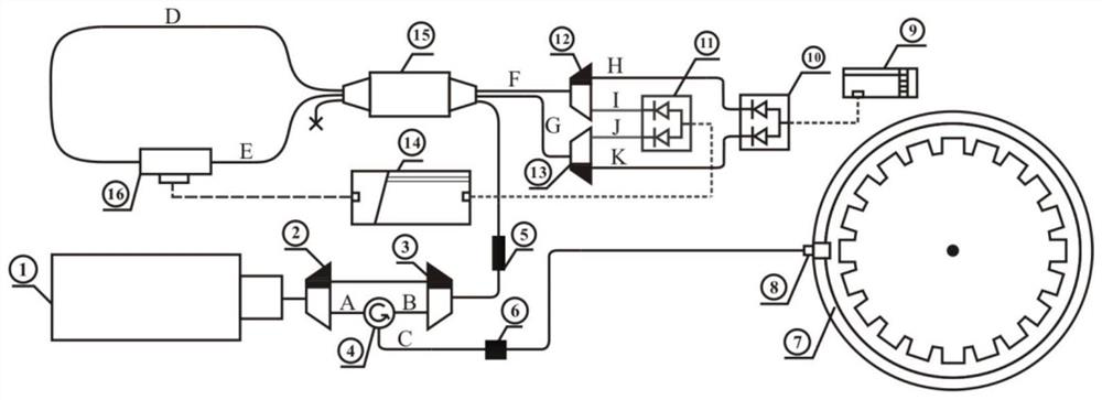
[0049] like figure 1 As shown, a high-precision and fast measurement device for engine tip clearance disclosed in this embodiment includes a mode-locked pulse laser 1, a wavelength division multiplexer 2, a wavelength division multiplexer 3, a looper 4, and an isolator 5. Delay line 6, aeroengine 7, probe 8, signal acquisition and processing device 9, balance detector 10, balance detector 11, demultiplexer 12, demultiplexer 13, signal locking device 14. 3×3 coupler 15 and electro-optic modulator 16.

[0050] The main function of the mode-locked pulsed laser 1 is to provide a beam of measurement light with a fixed-period and wide-spectrum ultrashort pulse laser, and the pulse width is on the order of femtoseconds.

[0051] The main function of the demultiplexer 2 is to separate the output light of the mode-locked pulsed laser 1 into two pulsed lights of different wavelengths, respectively λ 1 light and lambda 2 Light.

[0052] The main function of the wavelength division mu...


PUM


Abstract

The invention discloses a high-precision rapid measurement device and method for an engine blade tip gap, and belongs to the field of engine blade tip gap measurement. The high-precision rapid measurement device for an engine tip gag comprises a mode-locked pulse laser, a wavelength division demultiplexer, a loop unit, an isolator, a delay line, an aero-engine, a measuring head, a signal acquisition and processing apparatus, a balance detector, a wavelength division demultiplexer,a signal locking apparatus, a coupler and an electro-optical modulator. The invention further discloses a high-precision rapid measurement device and method for the engine blade tip gap. The measurement resolution is remarkably improved by combining the ultrashort mode-locked pulse laser and a Sagnac ring, the measurement value of the blade tip gap of each turbine blade can be obtained in the high-rotating-speed working state of the aero-engine, the highest measurement precision can reach the sub-nanometer magnitude, and a subsequent signal processing method is simple and efficient.

Description

technical field [0001] The invention relates to a high-precision and fast measuring device and method for engine blade tip clearance, belonging to the field of engine blade tip clearance measurement. Background technique [0002] Aeroengine tip clearance is the radial distance between the top of the rotor blade of the aeroengine and the inner wall of the case. During the operation of an aeroengine, the tip clearance of the rotor blade has a very important influence on the efficiency, safety and economy of the engine. If the blade tip clearance is too large, the leakage of the gap will increase, reducing the working efficiency of the engine and causing engine surge. If the blade tip clearance is too small, the collision friction between the rotor and the stator of the aeroengine will affect the safety and reliability. In severe cases, it will cause Engine damage. Therefore, the measurement of aeroengine tip clearance is one of the important measurement parameters in the pro...

Claims


Application Information

Patent Timeline
Patent Type & Authority Applications(China)
IPC IPC(8): G01B11/14
CPCG01B11/14
Inventor 赵春播武腾飞李润敏张磊韩继博
Owner BEIJING CHANGCHENG INST OF METROLOGY & MEASUREMENT AVIATION IND CORP OF CHINA
Why Eureka
Try Eureka