
Time domain comparator for ultralow-power-consumption successive approximation analog-to-digital converter

An analog-to-digital converter, successive approximation technology, applied in analog-to-digital conversion, code conversion, instruments, etc., can solve the problems of poor resistance to common-mode interference of input signals, not in the form of complementary differential input, and reducing the speed of comparators. Strong immunity to common mode level interference, high minimum voltage resolution, improved linearity

Active Publication Date: 2020-11-27
XI AN JIAOTONG UNIV
View PDF3 Cites 4 Cited by
  • Summary
  • Abstract
  • Description
  • Claims
  • Application Information

AI Technical Summary

Problems solved by technology

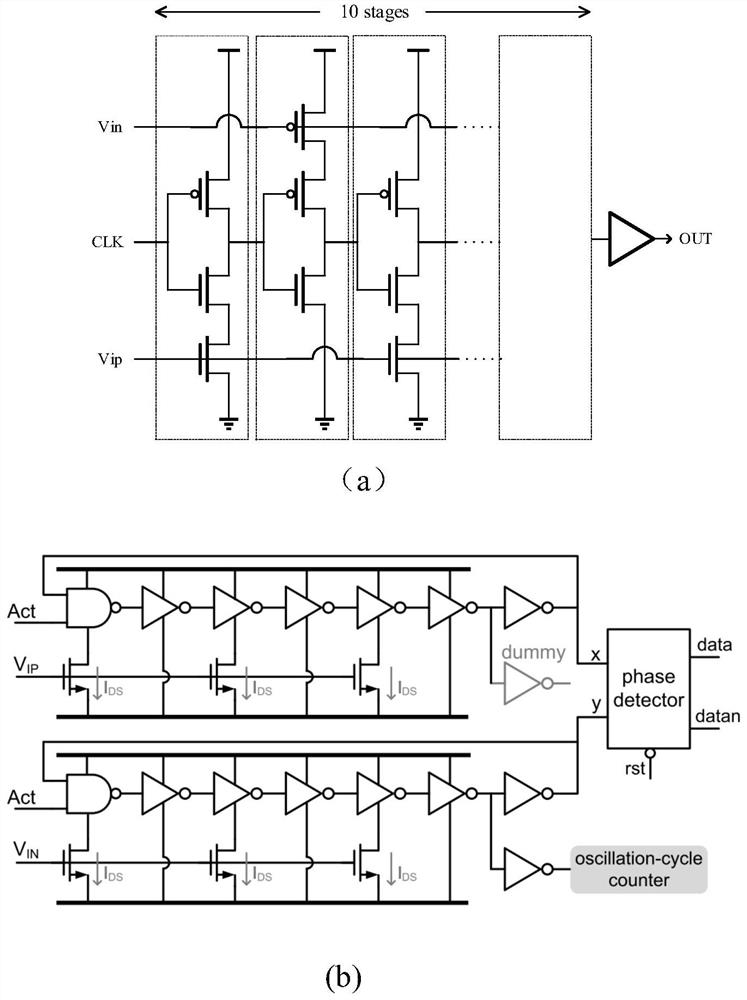
There is an open-loop time-domain comparator structure, such as figure 1 As shown in (a), the time-domain comparator achieves a large conversion gain by cascading multi-stage complementary differential voltage-controlled delay line units so that the circuit can work at a power supply voltage of 0.6V, but because the number of cascaded stages is small large so reduces the speed of the comparator
There is also a closed-loop time-domain comparator structure, such as figure 1 As shown in (b), the closed-loop time-domain comparator realizes the function of converting the voltage difference into a phase difference by cascading the same NMOS tube-controlled delay unit and inverter unit at the positive and negative signal input terminals, and the circuit is connected as In the closed-loop form, the number of cycles is controlled by the counter to reduce the dead time and improve the resolution of the minimum voltage difference. However, this structure is not a complementary differential input form, so the anti-common mode interference of the input signal is poor.

Method used


Image

  • Time domain comparator for ultralow-power-consumption successive approximation analog-to-digital converter
  • Time domain comparator for ultralow-power-consumption successive approximation analog-to-digital converter
  • Time domain comparator for ultralow-power-consumption successive approximation analog-to-digital converter

Examples


Embodiment Construction

[0033] In the description of the present invention, it should be understood that the terms "first" and "second" are used for description purposes only, and cannot be interpreted as indicating or implying relative importance or implicitly indicating the quantity of indicated technical features. Thus, a feature defined as "first" and "second" may explicitly or implicitly include one or more of these features. In the description of the present invention, unless otherwise specified, "plurality" means two or more.

[0034] In the description of the present invention, it should be noted that unless otherwise specified and limited, the terms "installation", "connection" and "connection" should be understood in a broad sense, for example, it can be a fixed connection or a detachable connection. Connected, or integrally connected; it may be mechanically connected or electrically connected; it may be directly connected or indirectly connected through an intermediary, and it may be the i...


PUM


Abstract

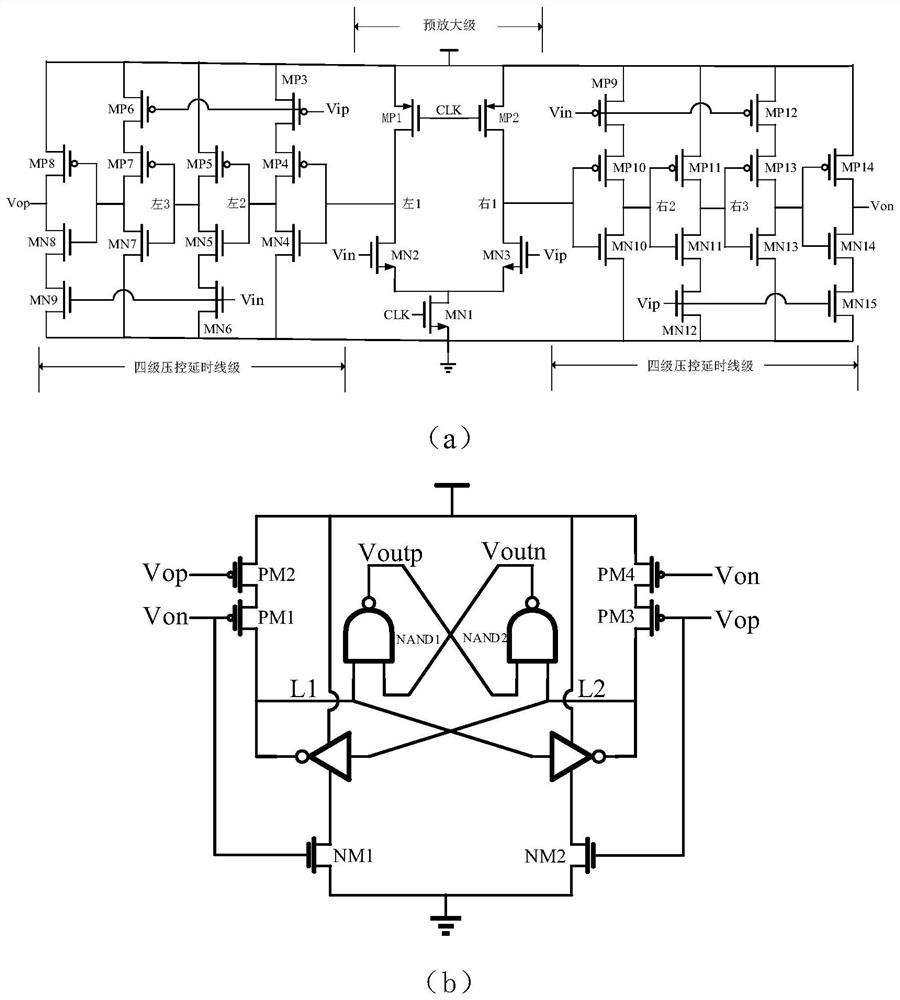
The invention discloses a time domain comparator for an ultralow-power-consumption successive approximation analog-to-digital converter. A voltage-time conversion circuit is connected with a phase discriminator circuit through a buffer, the voltage-time conversion circuit comprises a first-stage pre-amplification stage and second-stage four-stage complementary differential voltage control delay line stages, and the two four-stage complementary differential voltage control delay line stages are respectively connected with the pre-amplification stage and are used for complementing input signals.According to the invention, an open-loop time domain comparator structure is adopted; the voltage difference is converted into the phase difference by cascading the four-stage differential complementary voltage control delay line units through a preamplifier, the working speed of a comparator is higher due to the adoption of fewer cascading units, and meanwhile, the preamplifier is used, so thatthe common-mode level interference resistance is stronger, the whole circuit is simpler, and the power consumption is lower.

Description

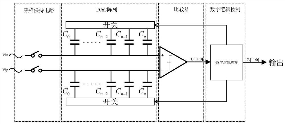
technical field [0001] The invention belongs to the technical field of analog integrated circuits, and in particular relates to a time-domain comparator for successive approximation analog-to-digital converters with ultra-low power consumption. Background technique [0002] Most of the signals in nature are analog quantities (sound, light, heat, etc.), and these signals are usually collected by analog circuits in the signal acquisition system, and then processed by digital circuits. The analog-to-digital converter is a bridge connecting the analog circuit and the digital circuit, so the power consumption, accuracy and speed of the analog-to-digital converter limit the performance of the entire signal acquisition system. In some low-power applications, such as the Internet of Things and bioelectrical signal acquisition, successive approximation analog-to-digital converters have great advantages. Such as figure 2 As shown, the successive approximation analog-to-digital conve...

Claims


Application Information

Patent Timeline
IPC IPC(8): H03M1/38
CPCH03M1/38
Inventor 桂小琰周小川袁刚郭宽田耿莉
Owner XI AN JIAOTONG UNIV
Learn More