

Sludge drying tail gas treatment system and process
A technology for exhaust gas treatment and sludge drying, applied in gas treatment, dispersed particle separation, membrane technology, etc., can solve the problem of secondary ozone pollution, and achieve the effect of short treatment route, increase contact time, and avoid secondary ozone pollution.
- Summary
- Abstract
- Description
- Claims
- Application Information
AI Technical Summary
Problems solved by technology
Method used
Image

Examples
Embodiment 1
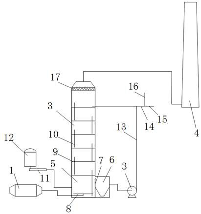
[0047] A sludge drying tail gas treatment system, such as figure 1 As shown, it includes a waste heat recovery device 1 , an exhaust gas treatment device 2 , a circulation pump 3 and an exhaust cylinder 4 . According to the flow direction of the sludge drying tail gas, the waste heat recovery device 1, the tail gas treatment device 2 and the exhaust pipe 4 are connected in sequence.
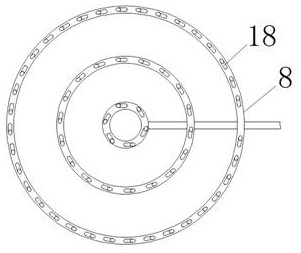
[0048] The tail gas treatment device includes a vertical tower body, a liquid storage tank 5 and an overflow chamber 6 are arranged at the bottom of the tower body, and an overflow plate 7 is arranged between the liquid storage tank 5 and the overflow chamber 6 . The bottom plate of the liquid storage tank 5 is provided with an aeration pan 8 , and the inlet of the aeration pan 8 is connected to the tail gas outlet of the waste heat recovery device 1 . Aeration discs, such as figure 2 As shown, it is formed by connecting several concentric annular pipes through the main pipe, and the pipe wall...
PUM
 Abstract
Description
Claims
Application Information