
Wellhead heating storage tank

A technology for heating storage tanks and storage tanks, which is applied to tank cars, containers, large containers, etc. It can solve problems such as difficult handling, rapid deterioration of heat transfer oil, and corrosion of furnace chambers, and achieve high heating safety, good thermal insulation performance, and improved temperature field Effect

Pending Publication Date: 2020-12-04
大庆市普罗石油科技有限公司
View PDF0 Cites 2 Cited by
  • Summary
  • Abstract
  • Description
  • Claims
  • Application Information

AI Technical Summary

Problems solved by technology

[0002] In crude oil production, the cost of laying gathering and transportation pipelines is too high for single-well oil production in remote areas. Crude oil storage tanks are installed at the wellhead to store the crude oil produced by the oil well, and then transported by tank trucks from the storage tanks to the tank trucks. For crude oil, the crude oil in the oil storage tank must be heated to a certain temperature. Therefore, the heating of the oil storage tank becomes the key to the normal production and cost of these oil wells. At present, the heating methods of single well tanks mainly include: heating with original heat transfer oil , built-in electric heating tube heating, etc. The original heat transfer oil heating method is safe and reliable, but there are disadvantages such as high energy consumption for bottom heating, serious corrosion to the furnace, rapid deterioration of heat transfer oil, and high failure rate. The dry heating method is low in cost, but it is safe. Poor performance, high energy consumption, short service life and other shortcomings;
[0003] Crude oil extracted from the wellhead is a mixture containing silt, impurities, water, etc. The silt accumulates in the storage tank and needs to be cleaned manually. layer, the upper part has a large proportion of crude oil, and the lower part contains more water, and the liquid in the entire storage tank is in an inhomogeneous state, which brings difficulties to subsequent processing;

Method used


Image

  • Wellhead heating storage tank
  • Wellhead heating storage tank

Examples


Embodiment Construction

[0015] The present invention will be further described below in conjunction with accompanying drawing:

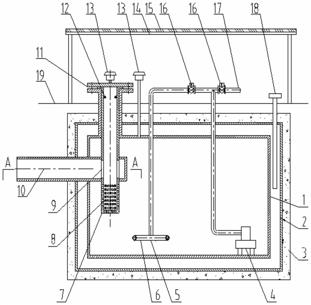
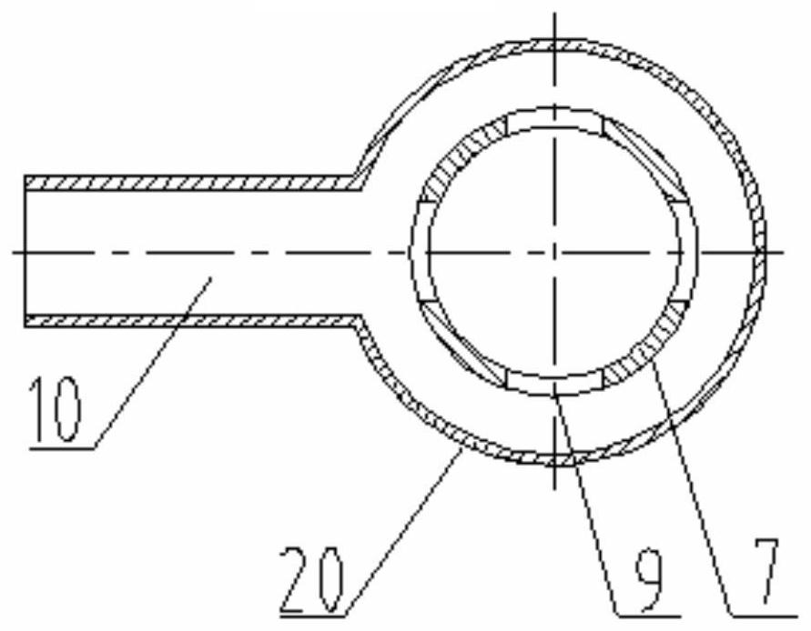
[0016] Depend on figure 1 combine figure 2 As shown, the wellhead heating storage tank includes a storage tank 1, and a water jacket 2 is arranged on the outside of the storage tank 1. The water jacket 2 is buried below the ground 19, and the soil is used as an external insulation layer to reduce the energy consumption of the storage tank 1. The water jacket 2 There is an electric heater 18 inside, and the electric heater 18 is used to heat the water in the water jacket 2 and indirectly heat the production fluid in the storage tank 1. The heating safety is high, and the purpose of flowing and exporting is achieved, preventing the electric heater from 18 directly heats the crude oil, the surface of the electric heater 18 is overheated, and the crude oil evaporates to cause a safety hazard of oil gas deflagration;

[0017] The storage tank 1 is provided with an external tr...


PUM


Abstract

The invention provides a wellhead heating storage tank, and relates to the technical field of oil extraction equipment. A water jacket is arranged on the outer side of the storage tank and buried underground, and an electric heater is arranged in the water jacket; an output pump is arranged in the storage tank, and an outlet of the output pump is connected with two electric valves in parallel andconnected with an output pipe and a back flushing pipe. The wellhead heating storage tank has the following advantages that produced liquid in the storage tank is indirectly heated, the heating safetyis high, the purpose of flowing output is achieved, and potential safety hazards caused by the fact that crude oil is directly heated by the electric heater are prevented; a spray head arranged at the bottom of the storage tank impacts liquid at the bottom of the storage tank upwards to form hydraulic stirring, the liquid in the whole storage tank is stirred and output in a homogeneous state, thetendency of impurity deposition at the bottom of the storage tank is reduced, and the homogeneous produced liquid is beneficial for subsequent treatment; terrestrial heat is stored and released through the energy storage performance of a phase change energy storage material, and the temperature field outside the water jacket is improved; and meanwhile, energy is supplemented to the storage tank through solar energy, and energy consumption is reduced.

Description

Technical field: [0001] The invention relates to the technical field of oil production equipment, in particular to a wellhead heating storage tank. Background technique: [0002] In crude oil production, the cost of laying gathering and transportation pipelines is too high for single-well oil production in remote areas. Crude oil storage tanks are installed at the wellhead to store the crude oil produced by the oil well, and then transported by tank trucks from the storage tanks to the tank trucks. For crude oil, the crude oil in the oil storage tank must be heated to a certain temperature. Therefore, the heating of the oil storage tank becomes the key to the normal production and cost of these oil wells. At present, the heating methods of single well tanks mainly include: heating with original heat transfer oil , built-in electric heating tube heating, etc. The original heat transfer oil heating method is safe and reliable, but there are disadvantages such as high energy co...

Claims


Application Information

Patent Timeline
Patent Type & Authority Applications(China)
IPC IPC(8): B65D88/76B65D88/74B65D90/00B65D88/54B65D90/02
CPCB65D88/76B65D88/744B65D90/00B65D88/54B65D90/028Y02A20/00
Inventor 柳子龙张庆会曲元峰
Owner 大庆市普罗石油科技有限公司
Learn More