A kind of method for sludge resource treatment

A sludge treatment and recycling technology, applied in sludge treatment, water/sludge/sewage treatment, dehydration/drying/concentrated sludge treatment, etc., can solve the problems of breeding stock disturbance, waste of resources, etc., and reduce bad impact, reduce turbidity, and realize the effect of resource treatment

Active Publication Date: 2022-07-15
CHONGQING TECH & BUSINESS UNIV
View PDF6 Cites 0 Cited by
  • Summary
  • Abstract
  • Description
  • Claims
  • Application Information

AI Technical Summary

Problems solved by technology

[0004] The purpose of the present invention is to provide a method for sludge resource treatment, which has solved the problem that the existing sludge treatment method will cause great disturbance to the breeding pool and cause waste of resources

Method used


Image

  • A kind of method for sludge resource treatment
  • A kind of method for sludge resource treatment

Examples


Embodiment 1

[0040] A method for sludge resource treatment, comprising the steps of:

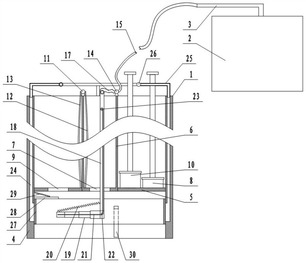
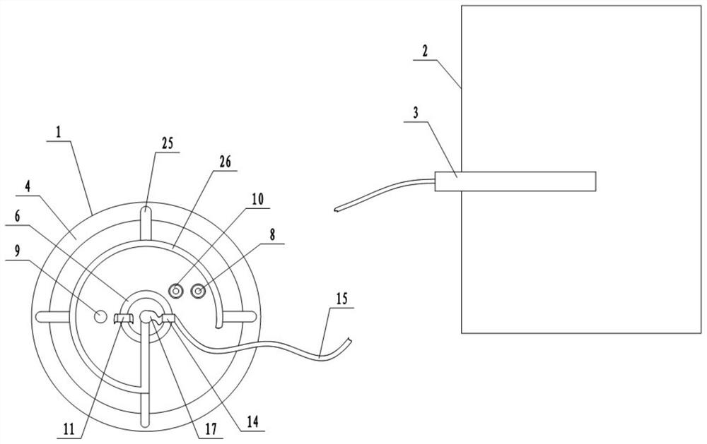
[0041] Step 1: Prepare the sludge treatment system: combine the attached figure 1 and attached figure 2 As shown, the sludge treatment system includes a sludge extraction device 1, a sludge flocculation device 2 and a connecting pipe 3 for connecting the sludge extraction device 1 and the sludge flocculation device 2. The sludge extraction device 1 is mainly composed of a partition cylinder 4 , a partition plate 5, an inner cylinder 6, a first sealing plug 8, a second sealing plug 10, a water pumping unit, and a first extraction unit. The bottom of the partition cylinder 4 is welded with a partition plate 5 made of transparent material. The separation plate 5 is 8-10 cm away from the bottom end of the separation cylinder 4 . The partition plate 5 divides the partition cylinder 4 into a pool water part and a sludge part, and the pool water part is located above the sludge part. The inner cylinder 6 is...

Embodiment 2

[0054] The difference between this embodiment and Embodiment 1 is that the sludge treatment system in step 1 further includes a second extraction unit, which is arranged on the separating cylinder 4 and is used to assist in extracting sludge. combined with figure 1 and attached figure 2 As shown, the second extraction unit is mainly composed of several pipe holes 24, several branch pipes 25, and a confluence pipe 26. Several pipe holes 24 are evenly distributed in the side wall of the separating cylinder 4 and are arranged longitudinally. L-shaped, branch pipes 25 are fixedly installed on the top of the pipe hole 24, all the branch pipes 25 are connected with a confluence pipe 26, and the confluence pipe 26 is communicated with the rigid section 18 of the mud inlet pipe; the bottom opening of the pipe hole 24 is set at a distance from The bottom 1-3 cm of the cylinder body 4 is separated and communicated with the sludge part. The sludge part is provided with a sealing unit f...


PUM


Abstract

The application relates to the technical field of aquaculture sludge treatment, and discloses a method for sludge resource treatment, comprising the following steps: step 1: preparing a sludge treatment system; step 2: separating the area for sludge to be extracted; Step 3: Separate the pool water and sludge; Step 4: Evacuate the inner cylinder; Step 5: Extract the sludge; Step 6: Flocculation and stratification; Step 7: Resource treatment; The rest of the library is processed. The method of the application can greatly reduce the disturbance caused to the aquaculture reservoir when the sludge is extracted, basically not cause the turbidity of the pool water in the aquaculture reservoir, and greatly reduce the release of pollutants in the sludge into the pool water with the disturbance. It is possible to avoid secondary pollution of the breeding warehouse; it does not need to spread or accumulate the sludge, and it does not need to occupy a large amount of agricultural land to accumulate the sludge. It occupies a small area and has strong practicability.

Description

technical field [0001] The invention belongs to the technical field of aquaculture sludge treatment. Background technique [0002] In recent years, the aquaculture industry has been vigorously developed and achieved certain economic benefits. However, with the long-term use of the aquaculture silo and the increase in aquaculture volume, a large amount of manure has accumulated at the bottom of the aquaculture silo, resulting in a gradual increase in the sludge at the bottom of the aquaculture silo and a gradual decrease in the water storage capacity of the aquaculture silo. Therefore, cleaning up the sludge at the bottom of the aquaculture silo is an urgent problem to be solved. [0003] At present, the cleaning of sludge is basically carried out by directly extracting it and spreading it on the farmland or the open space on the bank of the breeding warehouse. Using this method to clean the sludge, on the one hand, will cause great disturbance to the aquaculture pond, the ...

Claims


Application Information

Patent Timeline
Patent Type & Authority Patents(China)
IPC IPC(8): C02F11/121C02F11/14A01K63/10C02F103/20
CPCC02F11/121C02F11/14A01K63/10C02F2103/20
Inventor 齐高相黄冬梅申渝王建辉陈佳
Owner CHONGQING TECH & BUSINESS UNIV
Why Eureka
Try Eureka