Vacuum cavity structure

A vacuum cavity and cavity technology, which is applied in the field of OLED vacuum evaporation, can solve the problems of affecting production capacity and time-consuming, etc., and achieve the effects of increasing production capacity, improving evaporation quality, and improving device life

Pending Publication Date: 2020-12-04
FUJIAN HUAJIACAI CO LTD
View PDF0 Cites 0 Cited by
  • Summary
  • Abstract
  • Description
  • Claims
  • Application Information

AI Technical Summary

Problems solved by technology

Existing evaporation chambers inevitably need to be regularly opened for crucible feeding, crystal oscillator replacement, anti-sticking plate, angle plate replacement, etc. Frequent opening and closing of the chamber will have a great impact on the environment in the chamber, and large chambers will be removed from the atmosphere. It takes a long time to evacuate the state to a high vacuum, which affects the production capacity

Method used


Image

  • Vacuum cavity structure

Examples


Embodiment Construction

[0020] In order to explain in detail the technical content, structural features, achieved goals and effects of the technical solution, the following will be described in detail in conjunction with specific embodiments and accompanying drawings.

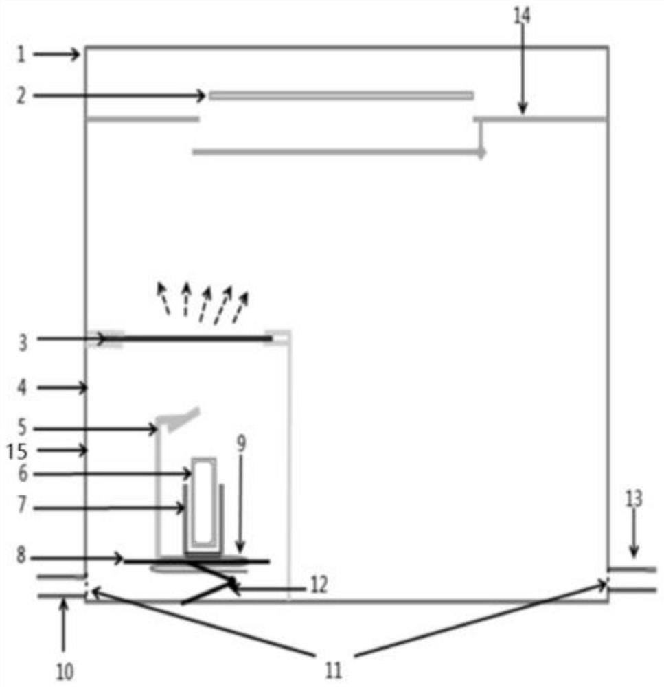
[0021] see figure 1 , this embodiment provides a vacuum cavity structure, which is characterized in that it includes: a mother cavity 1, a sub-cavity 4; the sub-cavity 4 is located on one side of the parent cavity 1, and placed On the side wall of the mother cavity 1; the mother cavity 1 includes: the main louver 14, the vacuum pipeline 13 of the mother cavity, and the mask plate 2; in some embodiments, the main louver 14 and the mask plate 2 can be omitted. The main louver 14 is located in the mother cavity 1 and is arranged above the sub-cavity 4, and the opening of the main louver 14 is set toward the direction of the sub-cavity 4; the mask plate 2 window Located in the mother cavity 1 and placed above the main shutter 14, the mo...


PUM


Abstract

The invention discloses a vacuum cavity structure. The vacuum cavity structure comprises a primary cavity and a secondary cavity, wherein the secondary cavity is positioned on one side in the primarycavity and is arranged on the side wall of the primary cavity; the primary cavity comprises a primary cavity vacuum pipeline; the primary cavity vacuum pipeline is connected to the primary cavity; thesecondary cavity comprises a sealing door, a visible door, a carrying table, a crucible heating device and a secondary cavity vacuum pipeline; the carrying table is arranged in the secondary cavity,and the crucible heating device is arranged above the carrying table and used for heating a crucible; the secondary vacuum pipeline is connected to the secondary cavity; the visible door is movably arranged on a cavity wall shared by the secondary cavity and the primary cavity; and the sealing door is movably arranged at the top of the secondary cavity. According to the vacuum cavity structure, when an abnormality occurs, the secondary cavity and the primary cavity can be subjected to vacuum breaking and cavity opening independently, so that the downtime is shortened. Therefore, the evaporation quality is improved, and meanwhile, the productivity of an evaporator is improved.

Description

technical field [0001] The invention relates to the technical field of OLED vacuum evaporation, in particular to a vacuum chamber structure. Background technique [0002] In recent years, with the rapid development of OLED technology, more and more liquid crystal display panels have been replaced by OLED panels. OLED screens have absolute advantages in color gamut and contrast, and evaporation is one of the core processes of OLED. At present, vacuum evaporation is used to prepare OLED devices. Vacuum evaporation is the process of evaporating or sublimating the material to be filmed (evaporation material) in a high vacuum, so that it is deposited on the surface of the workpiece or substrate. The film is because the organic film and metal film of the OLED device will be oxidized immediately after encountering water or air, so that the performance of the device will drop rapidly, and it is difficult to form a uniform and continuous film in a non-vacuum state due to the collisio...

Claims


Application Information

Patent Timeline
Patent Type & Authority Applications(China)
IPC IPC(8): C23C14/24C23C14/56C23C14/04
CPCC23C14/042C23C14/24C23C14/56C23C14/564
Inventor 张铭今孙玉俊
Owner FUJIAN HUAJIACAI CO LTD
Why Eureka
Try Eureka