Staged catalyst for abandoned coal gasification operation in fire zone, and preparation method thereof
A catalyst and coal gasification technology, which is applied in the direction of catalyst activation/preparation, physical/chemical process catalysts, chemical instruments and methods, etc., can solve problems such as ineffective effects, achieve reduced activation energy, increase contact area, and simple preparation process Effect
- Summary
- Abstract
- Description
- Claims
- Application Information
AI Technical Summary
Problems solved by technology
Method used
Image
Examples
Embodiment 1
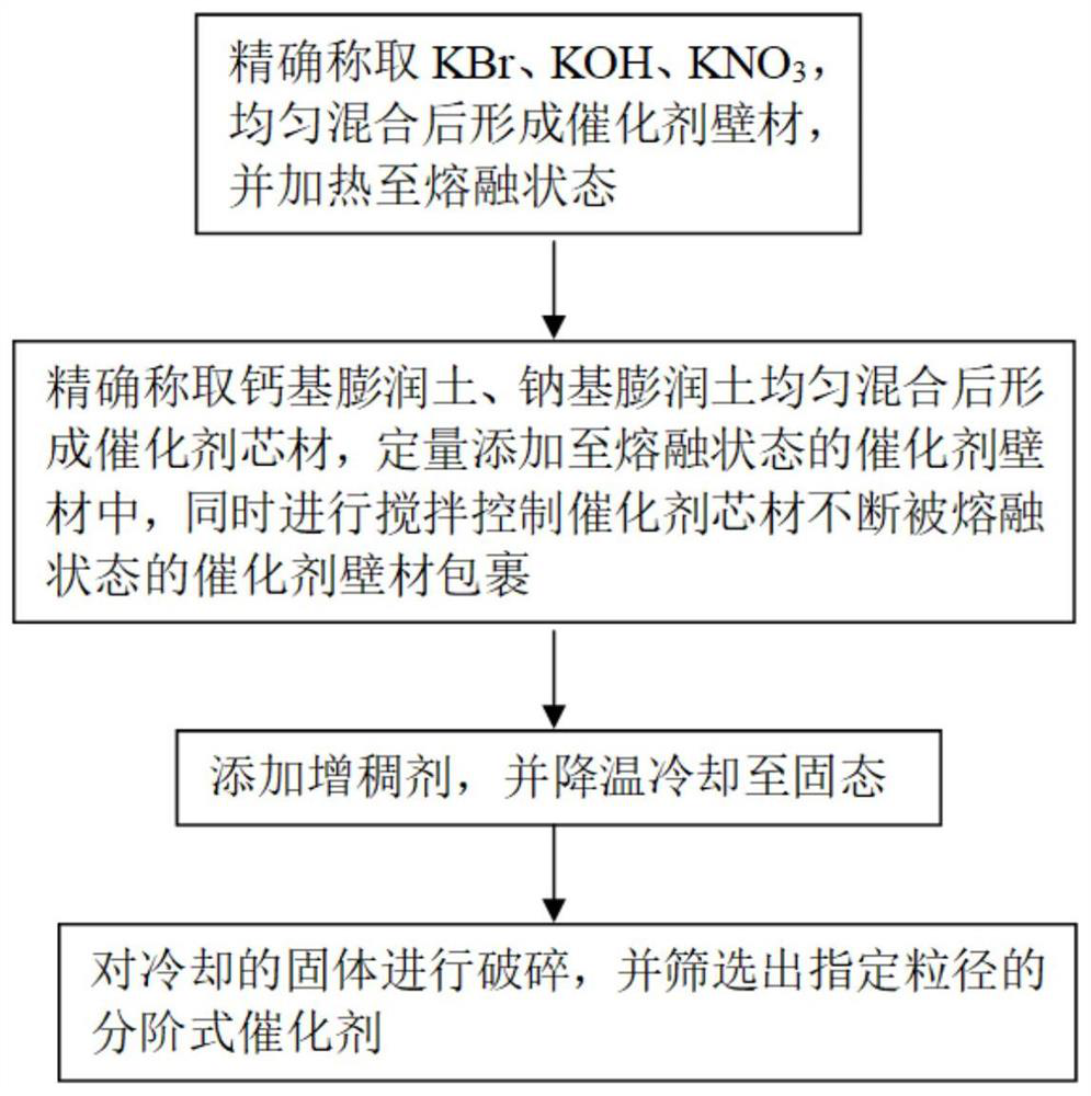
[0031] The catalyst core material selected in this embodiment is 21g calcium-based bentonite and 9g sodium-based bentonite; the selected catalyst wall material is 2.7g of KBr (melting point is about 510°C), 9.3g of KOH (melting point is about 380°C), 18g KNO 3(The melting point is about 334°C). The mass ratio of the catalyst core material and the catalyst wall material of the obtained hierarchical catalyst is 1:1. When the temperature exceeds 450°C, the catalyst wall material melts and ruptures to release the catalyst core material wrapped in it.
[0032] The graded catalyst that present embodiment is made carries out performance test, and result is as follows:
[0033] When the temperature of the prepared hierarchical catalyst rises to 450-480°C, the catalyst wall material begins to melt gradually. When the temperature exceeds 480°C, all the catalyst wall materials become molten, and the catalyst core material wrapped inside begins to melt. released to achieve the desired e...
Embodiment 2
[0044] The catalyst core material selected in this embodiment is 18g calcium-based bentonite and 12g sodium-based bentonite; the selected catalyst wall material is 2.4g of KBr (melting point is about 510°C), 12g of KOH (melting point is about 380°C), 15.6g KNO 3 (The melting point is about 334°C). The mass ratio of the catalyst core material to the catalyst wall material of the obtained hierarchical catalyst is 1:3.75. When the temperature exceeds 420°C, the catalyst wall material melts and ruptures to release the catalyst core material wrapped in it.
[0045] The graded catalyst that present embodiment is made carries out performance test, and result is as follows:
[0046] When the temperature of the prepared hierarchical catalyst rises to 400-450°C, the catalyst wall material begins to melt gradually. When the temperature exceeds 450°C, all the catalyst wall materials become melted, and the catalyst core material wrapped inside begins to melt. released to achieve the desi...
Embodiment 3
[0051] The catalyst core material selected in this embodiment is 19g calcium-based bentonite and 11g sodium-based bentonite; the selected catalyst wall material is 3g of KBr (the melting point is about 510°C), 12g of KOH (the melting point is about 380°C), and 15g of KNO 3 (The melting point is about 334°C). The mass ratio of the catalyst core material and the catalyst wall material of the obtained hierarchical catalyst is 1:2. When the temperature exceeds 480°C, the catalyst wall material melts and ruptures to release the catalyst core material wrapped in it.
[0052] The graded catalyst that present embodiment is made carries out performance test, and result is as follows:
[0053] When the temperature of the prepared step-by-step catalyst rises to 480-500°C, the catalyst wall material begins to melt gradually. When the temperature exceeds 500°C, all the catalyst wall materials become molten, and the catalyst core material wrapped inside begins to melt. released to achieve ...
PUM
| Property | Measurement | Unit |
|---|---|---|
| particle diameter | aaaaa | aaaaa |
| melting point | aaaaa | aaaaa |
| melting point | aaaaa | aaaaa |
Abstract
Description
Claims
Application Information
 - R&D
- Intellectual Property
- Life Sciences
- Materials
- Tech Scout
- Unparalleled Data Quality
- Higher Quality Content
- 60% Fewer Hallucinations
Browse by: Latest US Patents, China's latest patents, Technical Efficacy Thesaurus, Application Domain, Technology Topic, Popular Technical Reports.
© 2025 PatSnap. All rights reserved.Legal|Privacy policy|Modern Slavery Act Transparency Statement|Sitemap|About US| Contact US: help@patsnap.com


