Eureka AIR delivers breakthrough ideas for toughest innovation challenges, trusted by R&D personnel around the world.

A method for controlling the maximum torque-to-current ratio of an embedded permanent magnet synchronous motor

A technology of maximum torque current, permanent magnet synchronous motor, applied in motor control, motor generator control, electronic commutation motor control, etc. The effect of simplifying the system structure

Active Publication Date: 2022-03-22
JIANGSU UNIV
View PDF8 Cites 0 Cited by
  • Summary
  • Abstract
  • Description
  • Claims
  • Application Information

AI Technical Summary

Problems solved by technology

Although the look-up table method is relatively simple, its disadvantages are obvious, such as taking up a large amount of storage space, not being robust to motor parameters, etc.; the extreme value search method is more robust to motor parameters and is easier to implement , but the convergence time of the algorithm is long; and in the most widely used methods of signal injection, it is necessary to artificially inject a high-frequency and small-amplitude disturbance signal to track the MTPA point, which makes the high-frequency Noise is more obvious
At the same time, most signal injection methods inject the signal at the front end of the PI controller, and the frequency of the injected signal will be limited by the PI bandwidth.
Although the space vector signal injection method is to inject the signal into the inverter, the frequency of the injected signal is fixed. When the speed of the motor continues to increase and the fundamental frequency continues to rise, the frequency of the injected model may be different from that of the motor. Fundamental frequency mutual interference

Method used


Image

  • A method for controlling the maximum torque-to-current ratio of an embedded permanent magnet synchronous motor
  • A method for controlling the maximum torque-to-current ratio of an embedded permanent magnet synchronous motor
  • A method for controlling the maximum torque-to-current ratio of an embedded permanent magnet synchronous motor

Examples


Embodiment Construction

[0046] The technical solutions in the embodiments of the present invention will be clearly and completely described below in conjunction with the drawings in the embodiments of the present invention.

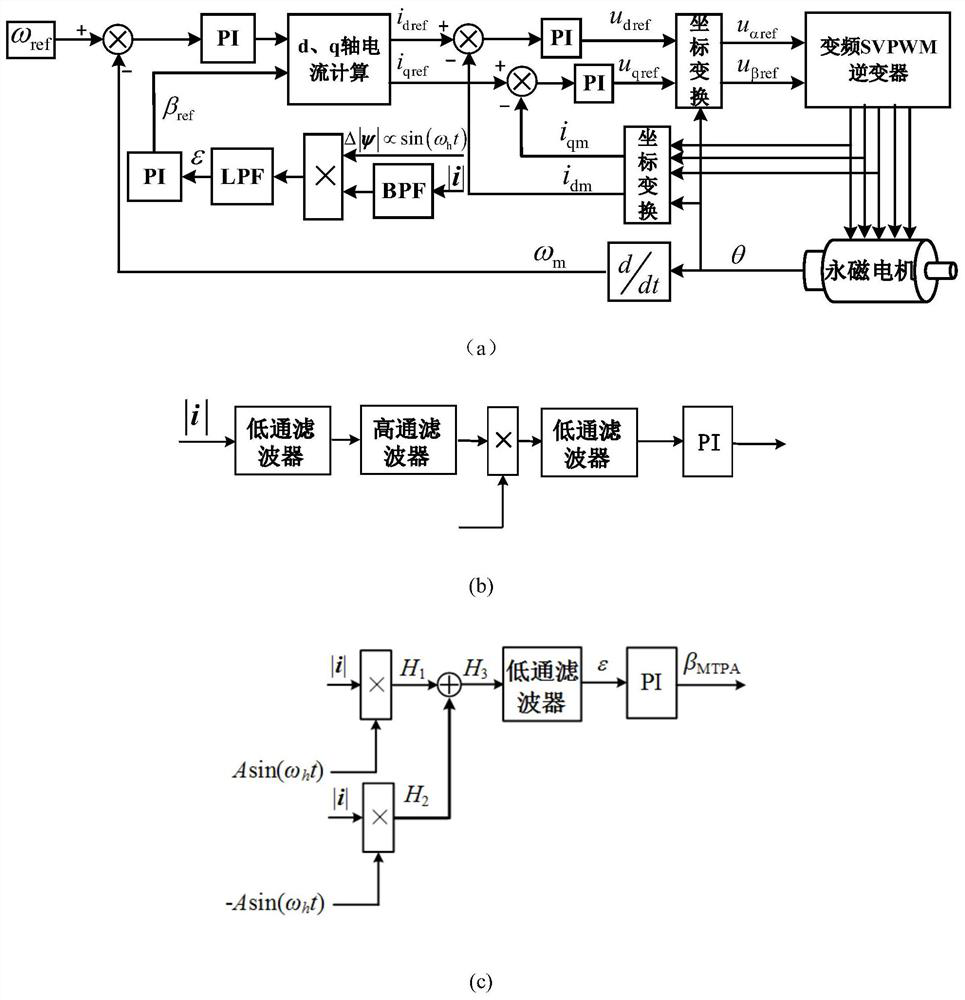
[0047] A method for controlling the maximum torque-to-current ratio of an embedded permanent magnet synchronous motor with variable frequency signal injection, comprising the following steps:

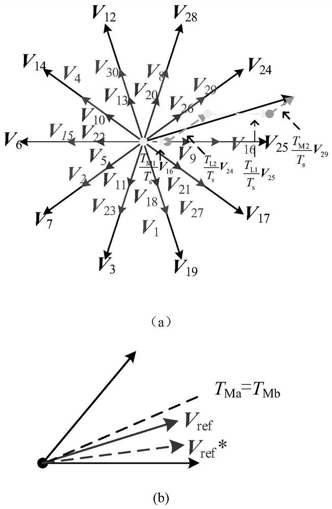
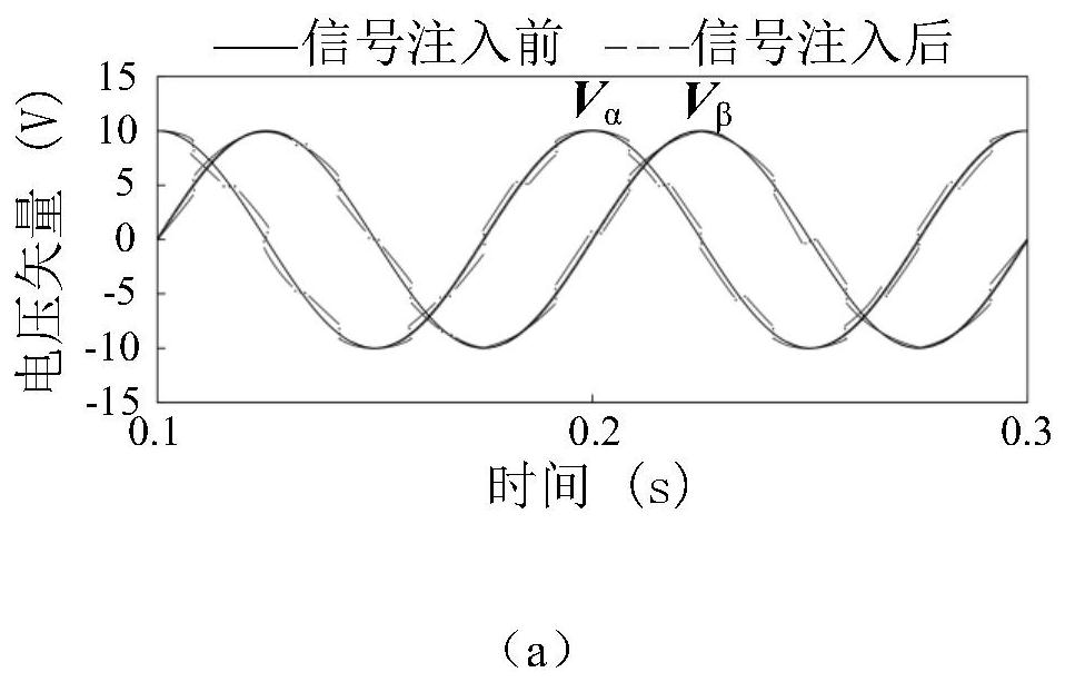
[0048] Step 1, when the reference voltage vector enters the space vector pulse width modulation algorithm to start vector synthesis, first judge the speed, adjust the action time of different vectors at different speeds, and generate the fundamental frequency of the motor in one electrical cycle a disturbance signal, which is injected directly into the motor;

[0049] Step 2, judge the sector, and adjust the vector action time of different sectors at different speeds. When the motor speed is less than 800r / min, it is necessary to adjust the two adjacent vectors in each of the ten sectors....


PUM


Abstract

The invention discloses a method for controlling the maximum torque-to-current ratio of a variable-frequency signal injected into an embedded permanent magnet synchronous motor, which includes: in the space vector pulse width modulation algorithm, by increasing or decreasing the effect of each medium vector in ten sectors Time, so that the reference voltage vector produces a phase lead or lag when it is synthesized, thereby forming a disturbance signal with a frequency multiple of the fundamental frequency of the motor, which is directly injected into the motor, and the disturbance signal will make the flux vector amplitude and current vector A disturbance of the same frequency is generated at the amplitude, and the d and q axis currents of the motor are determined by using the maximum torque current ratio point and the closed loop of the speed, and then the d and q axis voltages of the motor are obtained through the closed loop of the speed, and finally α, β-axis voltage, the voltage vector is synthesized in the SVPWM algorithm. The method can increase the frequency of the injected signal in multiples with the increase of the motor speed and the fundamental frequency, so that the frequency of the injected signal and the fundamental frequency of the motor will not interfere with each other.

Description

technical field [0001] The invention relates to the technical field of multi-phase motor maximum torque current ratio (MTPA) control, in particular to a method for implementing MTPA by injecting a variable frequency signal into an embedded permanent magnet synchronous motor based on a space vector pulse width modulation (SVPWM) algorithm. MTPA control is realized by injecting disturbance signals of different frequencies at different speeds of the motor. It is suitable for occasions that have high requirements on the performance and efficiency of motors such as aerospace, electric vehicles, and ship propulsion systems. Background technique [0002] Due to the advantages of high torque density and high efficiency factor, the embedded permanent magnet synchronous motor has gradually replaced a series of motors such as induction motors, and has become more and more important in military, aviation and household fields. Nowadays, energy saving and emission reduction have also bec...

Claims


Application Information

Patent Timeline
Patent Type & Authority Patents(China)
IPC IPC(8): H02P21/22H02P21/14H02P21/18
CPCH02P21/22H02P21/141H02P21/18H02P2205/01H02P2205/05H02P2205/07
Inventor 刘国海张嘉皓陈前赵文祥
Owner JIANGSU UNIV
Why Eureka
Eureka Blog
Learn More