A self-excited push-pull circuit and its auxiliary power supply method

An auxiliary power supply, self-excited push-pull technology, applied in electrical components, regulating electrical variables, output power conversion devices, etc. problem, to solve the effect of strong load capacity, reduced short-circuit power consumption, and reduced start-up voltage

Active Publication Date: 2022-07-19
MORNSUN GUANGZHOU SCI & TECH
View PDF4 Cites 0 Cited by
  • Summary
  • Abstract
  • Description
  • Claims
  • Application Information

AI Technical Summary

Problems solved by technology

When the input voltage of the product is small and the output voltage of the required auxiliary power supply circuit is large (in order to ensure that the product meets the load capacity), the above two auxiliary power supply circuit schemes cannot meet the circuit design requirements.
[0014] 2. In the self-excited push-pull topology, in general, the stronger the load capacity of the product, the greater the short-circuit power consumption when the product is short-circuited at the output end, resulting in reduced reliability of the product and increased risk of product failure
The two auxiliary power supply circuit schemes mentioned above cannot simultaneously solve the two contradictory design difficulties of strong load capacity and low short-circuit power consumption.

Method used


Image

  • A self-excited push-pull circuit and its auxiliary power supply method
  • A self-excited push-pull circuit and its auxiliary power supply method
  • A self-excited push-pull circuit and its auxiliary power supply method

Examples


no. 1 example

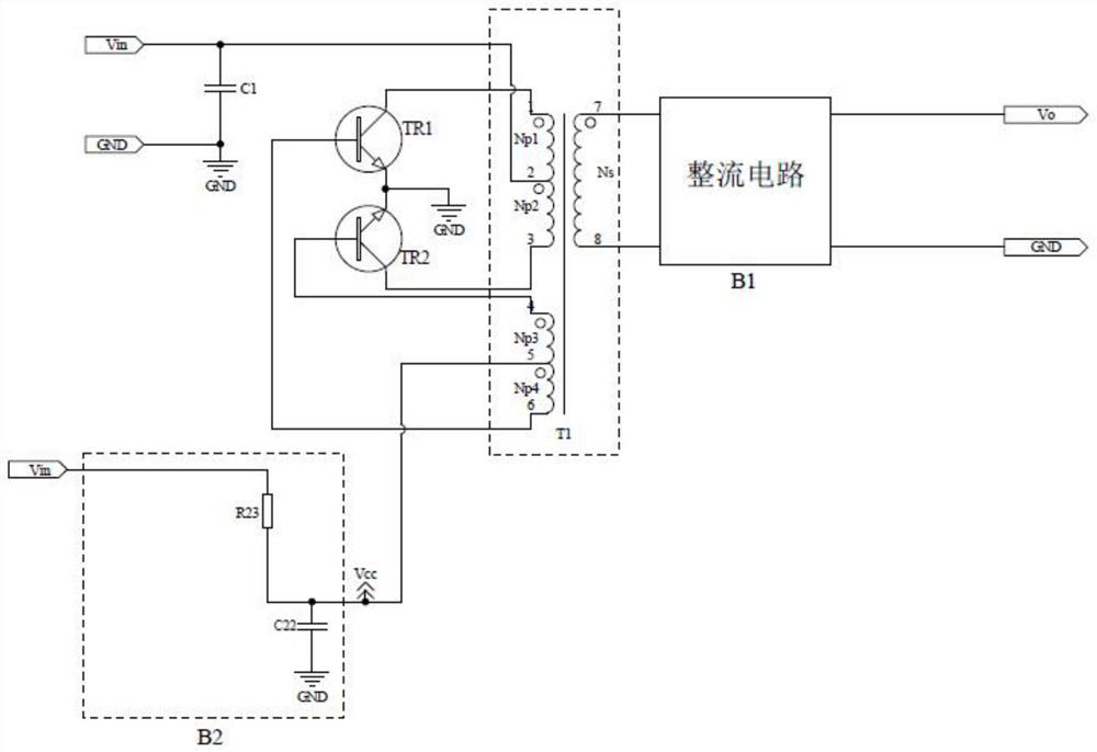
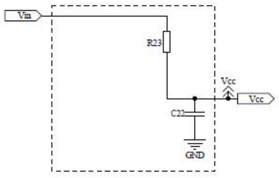
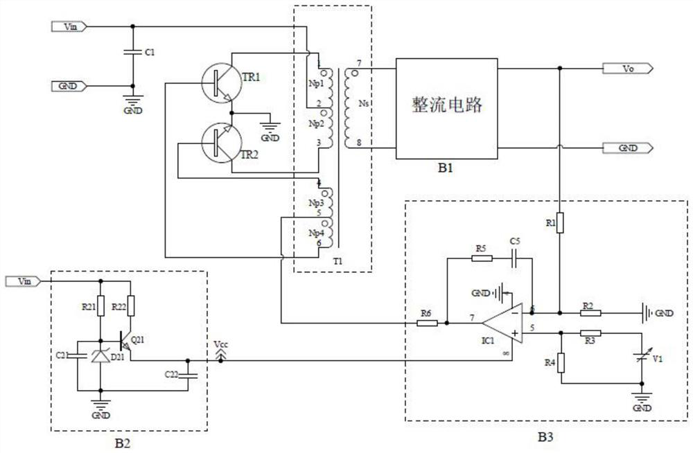
[0038] Figure 5 It is a schematic circuit diagram of a self-excited push-pull circuit of the present invention, including an input filter circuit, a main power circuit, a rectifier circuit, a feedback circuit and an auxiliary power supply circuit; wherein, the main power circuit includes a triode TR1, a triode TR2 and a transformer T1; the auxiliary power supply The circuit includes a diode D22 and a capacitor C22; the feedback circuit includes a resistor R1, a resistor R2, a resistor R3, a resistor R4, a resistor R5, a capacitor C5, an adjustable voltage source V1, an operational amplifier IC1 and a constant current source IC2;

[0039] The anode of the diode D22 is connected to the collector of the triode TR1, the connection point is the input end of the auxiliary power supply circuit, the cathode of the diode D22 is connected to one end of the capacitor C22, the connection point is the output end of the auxiliary power supply circuit, and the output end is connected to the ...


PUM


Abstract

The present invention provides a self-excited push-pull circuit, which includes a main power circuit and an auxiliary power supply circuit. The main power circuit includes a triode TR1, a triode TR2 and a transformer T1. The output end of the auxiliary power supply circuit is electrically connected to the center tap of the auxiliary winding of the transformer T1. , used to provide base current for transistors TR1 and TR2, characterized in that: the input end of the auxiliary power supply circuit is electrically connected to the collector of the transistor TR1 and / or the transistor TR2, which can reduce the short circuit of the product while enhancing the load capacity of the product power consumption. Compared with the prior art, the circuit of the present invention has the characteristics of less loss, higher output voltage than the input voltage of the product, taking into account the load capacity of the product and short-circuit power consumption, etc. Within the voltage range and wide temperature range, it can better meet the load capacity of the product and reduce the short-circuit power consumption under the short-circuit state of the output end of the product.

Description

technical field [0001] The invention relates to the field of switching power supplies, in particular to a self-excited push-pull circuit and an auxiliary power supply method for taking electricity from a triode collector. Background technique [0002] The self-excited push-pull topology is widely used in micro power supply applications because of its simple circuit and low switching noise. According to the application requirements of different occasions, the self-excited push-pull topology can be roughly divided into two types of manifestations, one is a constant voltage input open-loop feedback type, and the other is a closed-loop feedback voltage regulation type. [0003] like figure 1 As shown, the schematic diagram of the circuit is a constant voltage input open-loop feedback type, which is a widely used topology representation, including input filter circuit, main power circuit, rectifier circuit and auxiliary power supply circuit. The working principle of the circuit...

Claims


Application Information

Patent Timeline
Patent Type & Authority Patents(China)
IPC IPC(8): H02M3/338H02M1/096
CPCH02M3/3382H02M1/096
Inventor 刘洪金亮冯刚
Owner MORNSUN GUANGZHOU SCI & TECH
Why Eureka
Try Eureka