
Regenerative precoated sand roasting furnace

A roasting furnace and coated sand technology, which is applied in the direction of furnaces, furnace materials, furnace components, etc., can solve the problems of increasing the cost of sand roasting and increasing the amount of natural gas, and achieve the goal of reducing heat consumption, reducing ignition energy consumption, and reducing roasting costs Effect

Pending Publication Date: 2020-12-18
重庆市益环覆膜砂有限公司
View PDF0 Cites 0 Cited by
  • Summary
  • Abstract
  • Description
  • Claims
  • Application Information

AI Technical Summary

Problems solved by technology

[0003] When preparing coated sand by thermal method, the roasting furnace is used to roast the sand grains. When the sand grains enter the roasting furnace, they are cold sand grains. The cold sand grains need to consume more heat in the roasting furnace from low temperature to high temperature. Therefore, the consumption in the roasting furnace The amount of natural gas will increase, which will lead to an increase in the cost of sand roasting

Method used


Image

  • Regenerative precoated sand roasting furnace
  • Regenerative precoated sand roasting furnace
  • Regenerative precoated sand roasting furnace

Examples


Embodiment 1

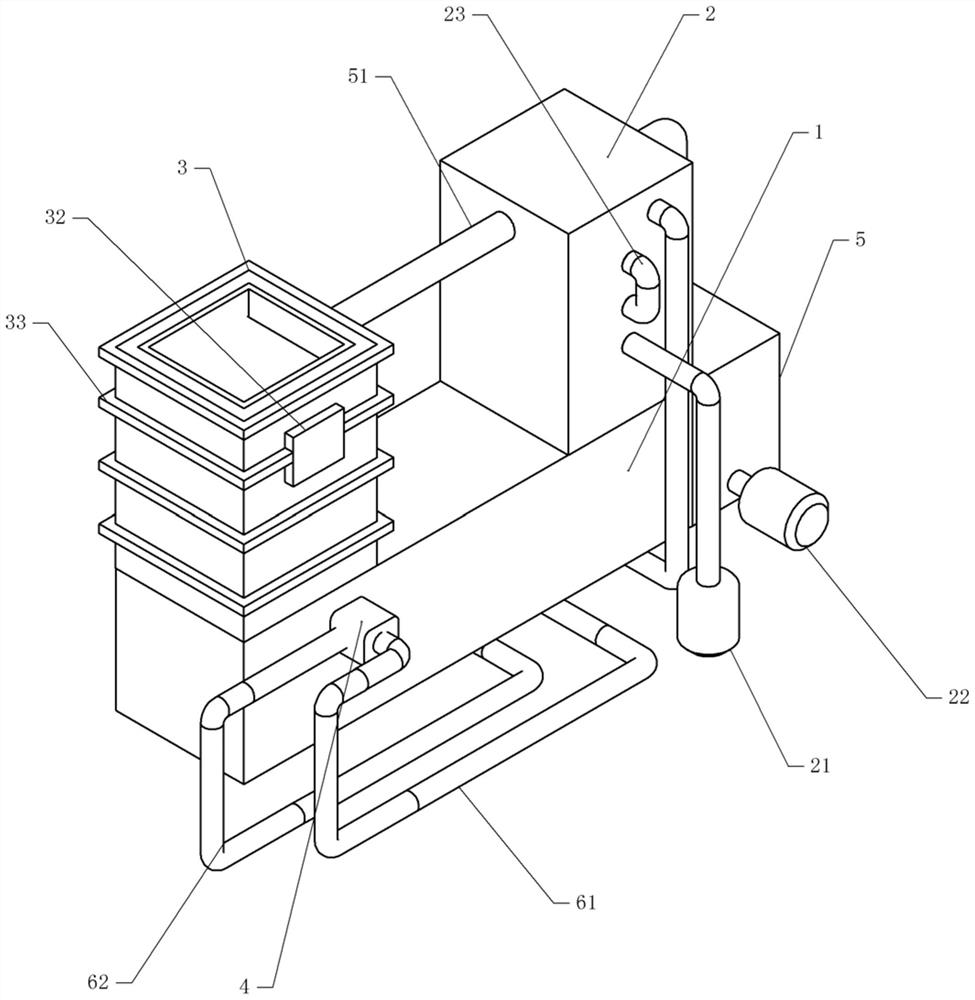
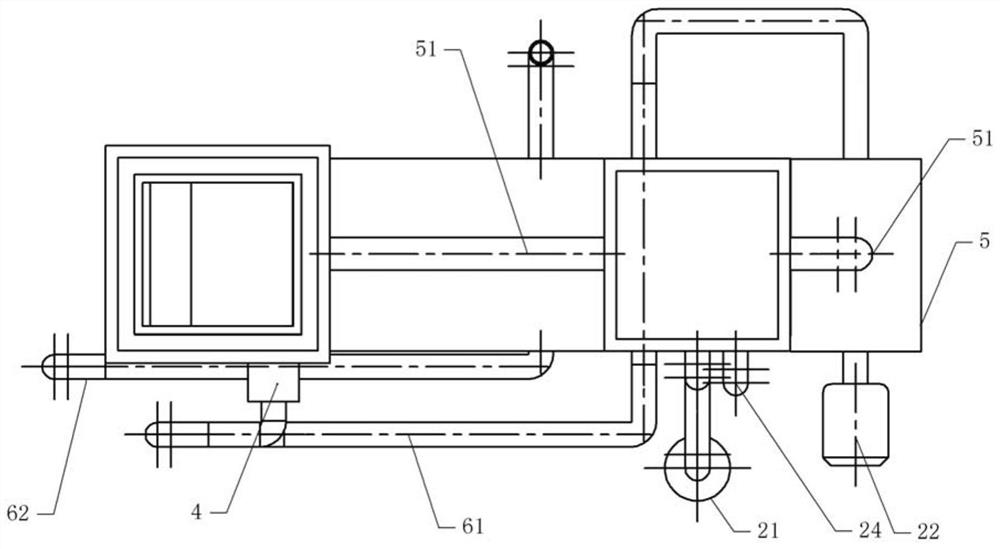
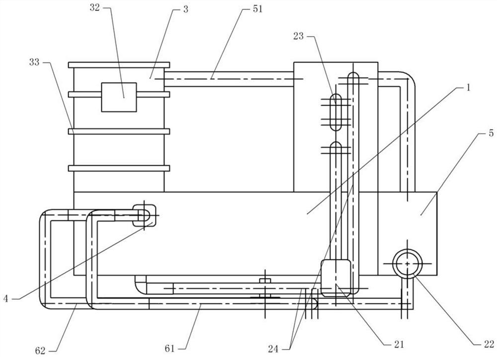
[0036] Basic as attached figure 1 , attached figure 2 , attached image 3 , attached Figure 4 And attached Figure 5 Shown: a regenerative coated sand roasting furnace, including a frame, on which a body 1 is fixed, one side of the body 1 is bolted to a feed chamber 3, and the other side of the body 1 is bolted to install a preheater Room 2.

[0037] In this embodiment, the upper and lower parts of the feeding chamber 3 are provided with openings, and the side walls of both sides in the feeding chamber 3 are fixed with several feeding plates 31 by bolts, and the feeding plates 31 on both sides are along the feeding The longitudinal direction of the chamber 3 is arranged in a staggered manner, and the feeding plate 31 is obliquely facing the middle of the feeding chamber 3, and the arrangement of the feeding plate 31 can form a deflector channel for sand particles to pass through. Bolts are fixed with some reinforcing plates 33 on the external side wall of feeding chambe...

Embodiment 2

[0049] The difference between embodiment two and embodiment one is that, as attached Figure 6 And attached Figure 7 As shown, there is a cavity 311 in the feed plate 31, and the cavity 311 is communicated with a number of air holes 312 evenly distributed on the feed plate 31. Air plates 313 are arranged in the air holes 312, and the air plates 313 are arranged obliquely. The end of 313 close to the upper surface of feed plate 31 is higher than the end of air plate 313 away from the upper surface of feed plate 31, the bottom of air plate 313 is provided with a spring, one end of the spring is fixed on the feed plate 31, and the other end of the spring is fixed On the air plate 313, several air holes are opened on the air plate 313, and the diameter of the air holes is smaller than the diameter of the sand grains. Cavity 311 is communicated with flexible pipe, and flexible pipe is communicated with air pump.

[0050] The specific implementation process is as follows:

[005...


PUM


Abstract

The invention relates to the technical field of precoated sand roasting energy conservation, and discloses a regenerative precoated sand roasting furnace. The regenerative precoated sand roasting furnace comprises a body, wherein a combustion chamber is arranged in the body, an igniter facing the interior of the combustion chamber is installed on the body, the regenerative precoated sand roastingfurnace comprises a feeding chamber fixed to one side of the body, one side of the combustion chamber communicates with the feeding chamber, the side, away from the feeding chamber, of the combustionchamber communicates with a preheating bag, and the preheating bag communicates with a waste gas pipe; a baffling channel is arranged in the feeding chamber, and a preheating cavity communicating withthe waste gas pipe is formed in the side wall of the feeding chamber; and the preheating cavity communicates with the waste gas pipe. The regenerative precoated sand roasting furnace is simple in structure, waste gas exhausted from the combustion chamber is fed into the feeding chamber to preheat sand, the sand with a certain temperature enters the combustion chamber, heat consumption in the combustion chamber can be reduced, then use of natural gas is reduced, and the roasting cost of the sand is reduced.

Description

technical field [0001] The invention relates to the technical field of coated sand roasting and energy saving, and specifically discloses a regenerative coated sand roasting furnace. Background technique [0002] Coated sand is the molding sand or core sand whose surface is covered with a layer of solid resin film. The preparation process of coated sand has two kinds of cold method and hot method: the cold method dissolves the resin with ethanol, and adds urotropine during the sand mixing process, so that the two are coated on the surface of the sand grains, and the ethanol volatilizes to obtain the coated sand. Coated sand: roast the sand to a certain temperature by thermal method, add resin to melt it, coat the resin on the surface of the sand by stirring, add urotropine aqueous solution and lubricant, cool, crush and sieve to obtain the coating Sand and coated sand are mainly used for steel castings and iron castings. [0003] When preparing coated sand by thermal metho...

Claims


Application Information

Patent Timeline
Patent Type & Authority Applications(China)
IPC IPC(8): B22C5/00F27D13/00F27D17/00
CPCB22C5/00F27D13/00F27D17/004F27M2003/02Y02P10/143
Inventor 张雪涛
Owner 重庆市益环覆膜砂有限公司
Learn More