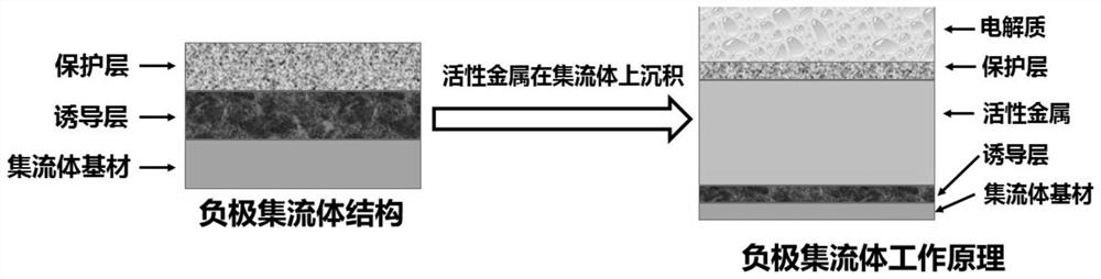
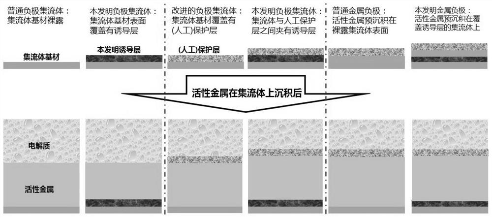
Negative electrode current collector as well as preparation method and application thereof
A technology of current collector and negative electrode, applied in the field of negative current collector, its preparation can solve the problems of reducing battery energy conversion efficiency, active material utilization rate battery cycle life, limiting battery application, shortening battery life and other problems
- Summary
- Abstract
- Description
- Claims
- Application Information
AI Technical Summary
Problems solved by technology
Method used
Image

Examples
Embodiment 1
[0082] This example is used to illustrate a preparation method of the negative electrode current collector of the present invention.
[0083] Preparation method: use low-temperature plasma surface treatment technology to inject carbon into the copper-based current collector to form Cu x C induction layer (x=0.1~5.0). in CH 4 As a carbon source, the workpiece temperature is 300-1000°C, and the back-bottom air pressure is 10 3 ~10 5 Pa, working air pressure 0.01-0.5Pa, gas source purity 99%-99.99%, injection dose 10 15 ~10 18 ions / cm 2 .
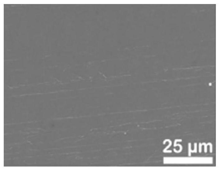
[0084] In a preferred embodiment, CH 4 As a carbon source, the workpiece temperature is 600°C, the back and bottom pressure is 2000Pa, the working pressure is 0.2Pa, the purity of the gas source is 99%, and the injection dose is 10 16 ions / cm 2 , forming an induced layer Cu with a thickness of 30 nm 2 c.
[0085] image 3 The morphology of the flat current collector substrate (foil) of Example 1 is shown.
Embodiment 2
[0087] This example is used to illustrate a preparation method of the negative electrode current collector of the present invention.
[0088] Preparation method: use low-temperature plasma surface treatment technology to inject carbon into the surface of stainless steel-based current collector to form Fe x C induction layer (x=0.1~5). Use CH 4 As a carbon source, the workpiece temperature is 300-1000°C, and the back-bottom air pressure is 10 3 ~10 5 Pa, working air pressure 0.01-0.5Pa, gas source purity 99-99.99%, injection dose 10 15 ~10 18 ions / cm 2 .
[0089] In a preferred embodiment, CH 4 As a carbon source, the workpiece temperature is 700°C, and the back-bottom air pressure is 10 4 Pa, working pressure 0.2Pa, gas source purity 99.5%, injection dose 5×10 16 ions / cm 2 , forming an induced layer of Fe with a thickness of 50 nm 2 c.
Embodiment 3
[0091] This example is used to illustrate a preparation method of the negative electrode current collector of the present invention.
[0092] Preparation method: use low-temperature plasma surface treatment technology to inject nitrogen into the surface of titanium-based current collector to form Ti x N induction layer (x=0.1~5). Use nitrogen (N 2 ) is the nitrogen source, the workpiece temperature is 300-1000°C, and the back-to-bottom air pressure is 10 3 ~10 5 Pa, working air pressure 0.01~0.5Pa, gas source purity 99.00~99.99%, injection dose 10 15 ~10 18 ions / cm 2 .
[0093] In a preferred embodiment, with nitrogen (N 2 ) is the nitrogen source, the workpiece temperature is 1000°C, and the back and bottom air pressure is 2×10 4 Pa, working air pressure 0.3Pa, gas source purity 99%, injection dose 10 16 ions / cm 2 , forming an induction layer TiN with a thickness of 20nm.
PUM
| Property | Measurement | Unit |
|---|---|---|
| Thickness | aaaaa | aaaaa |
| Thickness | aaaaa | aaaaa |
| Thickness | aaaaa | aaaaa |
Abstract
Description
Claims
Application Information
 - R&D
- Intellectual Property
- Life Sciences
- Materials
- Tech Scout
- Unparalleled Data Quality
- Higher Quality Content
- 60% Fewer Hallucinations
Browse by: Latest US Patents, China's latest patents, Technical Efficacy Thesaurus, Application Domain, Technology Topic, Popular Technical Reports.
© 2025 PatSnap. All rights reserved.Legal|Privacy policy|Modern Slavery Act Transparency Statement|Sitemap|About US| Contact US: help@patsnap.com