Magnetic steel spraying automatic production line

An automatic production line and production line technology, applied in spray booths, injection devices, etc., can solve the problems of limited anti-corrosion delay, life-threatening, acute poisoning and other problems of magnetic steel, and achieve the goal of eliminating hidden dangers of personal safety, improving processing efficiency, and improving production efficiency Effect

Pending Publication Date: 2020-12-25
沈阳新铭天合金材料有限公司
View PDF0 Cites 2 Cited by
  • Summary
  • Abstract
  • Description
  • Claims
  • Application Information

AI Technical Summary

Problems solved by technology

[0004] 1. Electroplating wastewater will be produced, which will have a greater impact on the environment
[0005] 2. Occupational diseases. Operators who have been engaged in electroplating for a long time may suffer from skin diseases, pharyngitis and other diseases, and have toxic effects on the central nervous system and peripheral nerves, and also have adverse effects on bone marrow hematopoietic function.
When electroplating with alkaline chromium salt, hydrogen cyanide may escape. If the cyanide in the plating solution encounters acid, high concentration hydrogen cyanide can be produced, which can cause acute poisoning or even life-threatening
[0006] 3. At present, some electroplating processes use non-environmentally friendly chemical raw materials, which will bring their chemical materials into the coating during electroplating, directly affecting the health of users
[0007] 4. The anti-corrosion delay of the electroplated magnetic steel is limited
[0008] 5. The magnet steel after electroplating does not have the property of high temperature resistance
Magnetic steel spraying requires multiple processes. If each process is completed manually, the quality and accuracy of the processing cannot be guaranteed, and the processing efficiency will also be limited by manual methods. Therefore, it is necessary to design an automatic production line for magnetic steel spraying. , to overcome the above technical problems

Method used


Image

  • Magnetic steel spraying automatic production line

Examples


Embodiment Construction

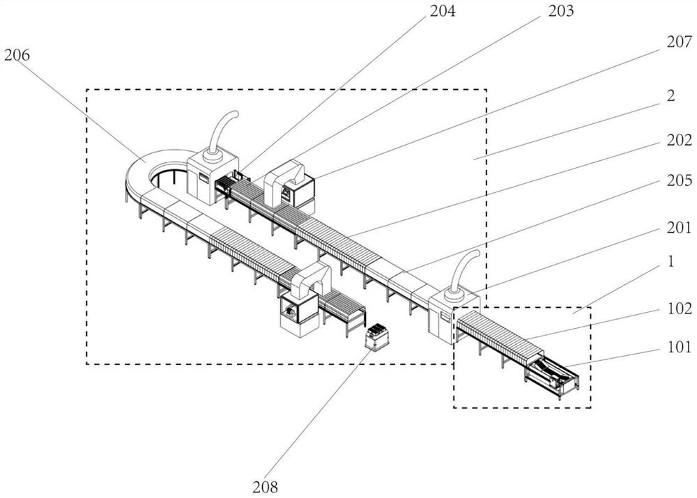
[0035] The present invention will be further explained below in conjunction with specific embodiments, but it does not limit the present invention. The structures, proportions, sizes, etc. shown in the accompanying drawings of the description are only used to match the content disclosed in the description, so as to facilitate familiarity with the present invention. Those skilled in the art understand and read that it is not used to limit the implementation of the present invention, so it has no technical significance. Any modification of structure, change of proportional relationship or adjustment of size will not affect the present invention. Under the effects and goals that can be achieved, all should still fall within the scope covered by the technical content disclosed in the present invention. At the same time, terms such as "upper", "lower", "front", "rear", and "middle" quoted in this specification are only for the convenience of description, and are not used to limit th...


PUM


Abstract

The invention discloses a magnetic steel spraying automatic production line. A cleaning area and a spraying area are included. .The cleaning area comprises a cleaning section and a drying section, thecleaning section is used for removing dirt on the surface of a workpiece, and the drying section is used for drying the cleaned workpiece The spraying area comprises two spraying sections, two thermocuring sections, two air cooling sections and a turnover device, the two spraying sections are used for spraying the surface of the workpiece, the two thermocuring sections are used for curing a coating formed after workpiece spraying, the two air cooling sections are used for cooling the workpiece in a high-temperature state, and the turnover device is used for turning over the workpiece. The connection relation among all the parts in the spraying area is the first spraying section, the first thermocuring section, the first air cooling section, the turnover device, the second spraying section, the second thermocuring section and the second air cooling section. The production line is simple in structure and automatic in operation, and the workpiece can be subjected to multi-layer sprayingaccording to actual requirements.

Description

technical field [0001] The invention belongs to the technical field of magnetic steel processing, and in particular relates to an automatic production line for magnetic steel spraying. Background technique [0002] Sintered NdFeB rare earth alloy magnets are composed of light rare earth elements and heavy rare earth elements. The composition of its metal components is different, its magnetic properties are different, and its uses are also different. It is mainly used in various sensors, instruments, electronics, electromechanical, medical, teaching, automotive, aviation, military technology and other fields. In recent years, NdFeB magnets, as a sunrise industry of energy conservation and environmental protection, have been widely used in information technology, automobiles, nuclear magnetic resonance, wind power generation and motors and other fields. [0003] NdFeB is produced by powder metallurgy process, and the neodymium element in it is easily oxidized, and it is easy ...

Claims


Application Information

Patent Timeline
Patent Type & Authority Applications(China)
IPC IPC(8): B05B16/20B05B13/02
CPCB05B13/0235B05B16/20
Inventor 苏荣欣苏霄天
Owner 沈阳新铭天合金材料有限公司
Why Eureka
Try Eureka