
Textile bleaching device

A textile and box technology, applied in the field of textile bleaching devices, can solve the problems of insufficient bleaching agent dissolution, affect the bleaching effect, and low bleaching rate, and achieve the goal of avoiding excessively high water temperature, increasing the bleaching effect, and increasing the bleaching efficiency Effect

Inactive Publication Date: 2020-12-25
朱官玲
View PDF0 Cites 2 Cited by
  • Summary
  • Abstract
  • Description
  • Claims
  • Application Information

AI Technical Summary

Problems solved by technology

[0004] The purpose of the present invention is to solve the problem in the prior art that the one-time addition of the bleaching agent leads to insufficient dissolution of the bleaching agent, which affects the bleaching effect, and is not convenient for stably heating the water, resulting in a low bleaching rate. Textile Bleaching Plant

Method used


Image

  • Textile bleaching device
  • Textile bleaching device
  • Textile bleaching device

Examples


Embodiment 1

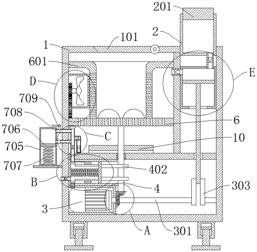
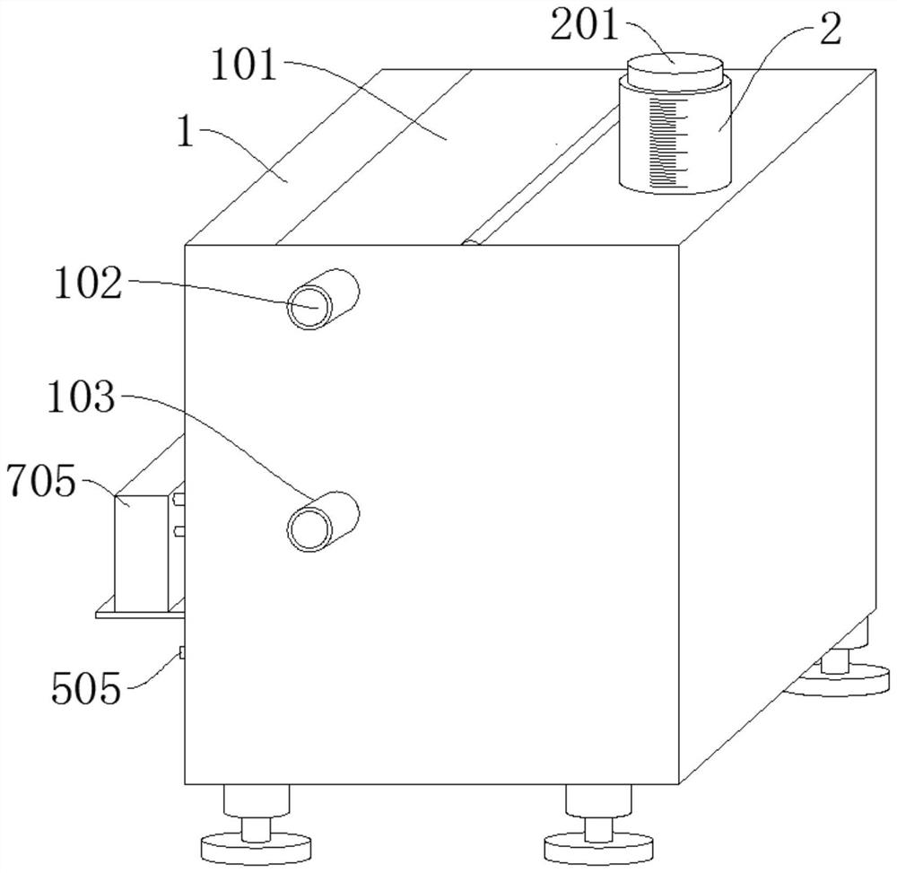
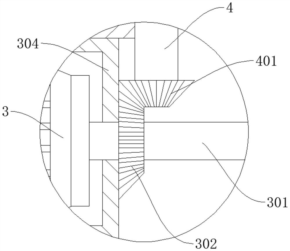
[0038] refer to Figure 1-7, a textile bleaching device, comprising a box body 1, a feeding pipe 2, a box door 101, the box door 101 is rotatably connected to the box body 1, the feeding tube 2 is fixedly connected to the box body 1, and the box body 1 is provided with There is a partition 11, a driving motor 3 is arranged in the box body 1, and the driving motor 3 is located under the partition 11. The output end of the driving motor 3 is fixedly connected to a rotating shaft 301, and a bevel gear 302 is arranged on the rotating shaft 301, and the rotating shaft 302 rotates in the box body 1. Connected with a rotating shaft 4, the lower end of the rotating shaft 4 is provided with a driven gear 401, the driven gear 401 meshes with the bevel gear 302, and the rotating disk 6 is connected to the inside of the box body 1, the rotating disk 6 is located above the partition 11, and the rotating disk 6 is fixed Connected to the end of the rotating shaft 4 away from the driven gear ...

Embodiment 2

[0041] refer to Figure 1-7 , a textile bleaching device, which is basically the same as in Example 1, furthermore, the side wall of the box body 1 is provided with an incubator 705, and a sealing plate 706 is slidably connected in the incubating box 705, between the sealing plate 706 and the incubating box 705 A second spring 707 is connected between them, an air guide pipe 703 is connected between the incubator 705 and the exhaust pipe 506, a pressure valve 704 is provided on the air guide pipe 703, an air jet pipe 708 is connected between the incubator 705 and the exhaust pipe 506, The jet pipe 708 is provided with a control valve 709. When the sealing block 702 seals the exhaust pipe 506, the air pressure in the exhaust pipe 506 increases, the pressure valve 704 opens, and the hot gas produced by the gas cylinder 5 flows along the exhaust pipe 506, the air guide pipe 703 enters the incubator 705. As the gas in the incubator 705 increases, the sealing plate 706 is pressed a...

Embodiment 3

[0043] refer to Figure 1-7 , a textile bleaching device, which is basically the same as that of Embodiment 1, furthermore, a dehydration bucket 601 is fixedly connected to the turntable 6, and the dehydration bucket 601 is rotatably connected in the box body 1, and the dehydration bucket 601 is densely covered with through holes to connect After the water in the tank 1 is discharged, the dehydration bucket 601 rotates with the turntable 6, and the water attached to the textile in the bucket is separated from the textile under the action of centrifugal force, and the separated water is discharged along the through hole, and is discharged out of the tank through the drain pipe 103. Body 1.


PUM


Abstract

The invention discloses a textile bleaching device, and belongs to the field of textile mechanical equipment. The textile bleaching device comprises a box body, a discharging pipe and a box door, wherein the box door is rotatably connected to the box body, the discharging pipe is fixedly connected to the box body, a partition plate is arranged in the box body, a driving motor is arranged in the box body and located below the partition plate, and a rotating shaft is fixedly connected to the output end of the driving motor; and a bevel gear is arranged on the rotating shaft. According to the bleaching device, through the arrangement of a rotary disc, water in the box body can be conveniently driven to flow in an accelerated mode, a bleaching agent can be conveniently and rapidly mixed and dissolved, the bleaching agent can be conveniently added for multiple times through the arrangement of a material guide barrel, it is guaranteed that the bleaching agent is fully mixed with water, and then the bleaching agent makes uniform contact with textile to avoid chromatic aberration; Through the arrangement of an air cylinder, a friction rod and a friction ring, the water is conveniently heated, the bleaching efficiency is improved, besides, the textile is conveniently dried, and through the arrangement of a control pipe, the water temperature is conveniently prevented from being too high.

Description

technical field [0001] The invention relates to the technical field of textile machinery and equipment, in particular to a textile bleaching device. Background technique [0002] Bleaching is the process of decomposing and decolorizing the colored substances in textiles by chemical action, so that the textiles can obtain the necessary whiteness. Textiles usually need to be dyed and then processed after bleaching. [0003] At present, artificial bleaching is mostly used. The textiles are placed in the bleaching tank, and the bleaching agent is added to the bleaching tank, the textiles are stirred for bleaching, and then the textiles are picked up and wrung out. The temperature of the water has a great influence on the bleaching agent The dissolution rate and the reaction rate of the bleach and the colored substance are greatly affected. When the water temperature is low, the bleach is not fully dissolved, the reaction speed of the bleach and the colored substance is slow, and...

Claims


Application Information

Patent Timeline
Patent Type & Authority Applications(China)
IPC IPC(8): D06B3/10D06B23/20D06B23/22D06B15/09D06B15/10D06B23/30
CPCD06B3/10D06B15/09D06B15/10D06B23/20D06B23/205D06B23/22D06B23/30
Inventor 朱官玲
Owner 朱官玲
Learn More