
Binocular vision three-dimensional scanning system

A three-dimensional scanning and binocular vision technology, applied in the field of three-dimensional scanning, can solve cumbersome problems, and achieve the effects of easy portability, improved use distance and range, and rapid molding.

Pending Publication Date: 2020-12-25
JIMEI UNIV
View PDF0 Cites 0 Cited by
  • Summary
  • Abstract
  • Description
  • Claims
  • Application Information

AI Technical Summary

Problems solved by technology

[0002] Three-dimensional scanning refers to a high-tech integration of optical, mechanical, electrical and computer technologies. It is mainly used to scan the spatial shape, structure and color of objects to obtain the spatial coordinates of the object's surface. The existing three-dimensional scanners are basically One-piece structure, when scanning objects, the scanner needs to be moved back and forth, which is cumbersome and has certain limitations in use

Method used


Image

  • Binocular vision three-dimensional scanning system
  • Binocular vision three-dimensional scanning system
  • Binocular vision three-dimensional scanning system

Examples


Embodiment 1

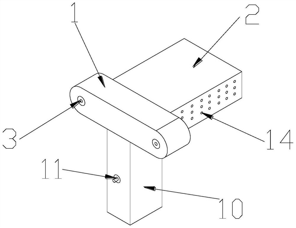
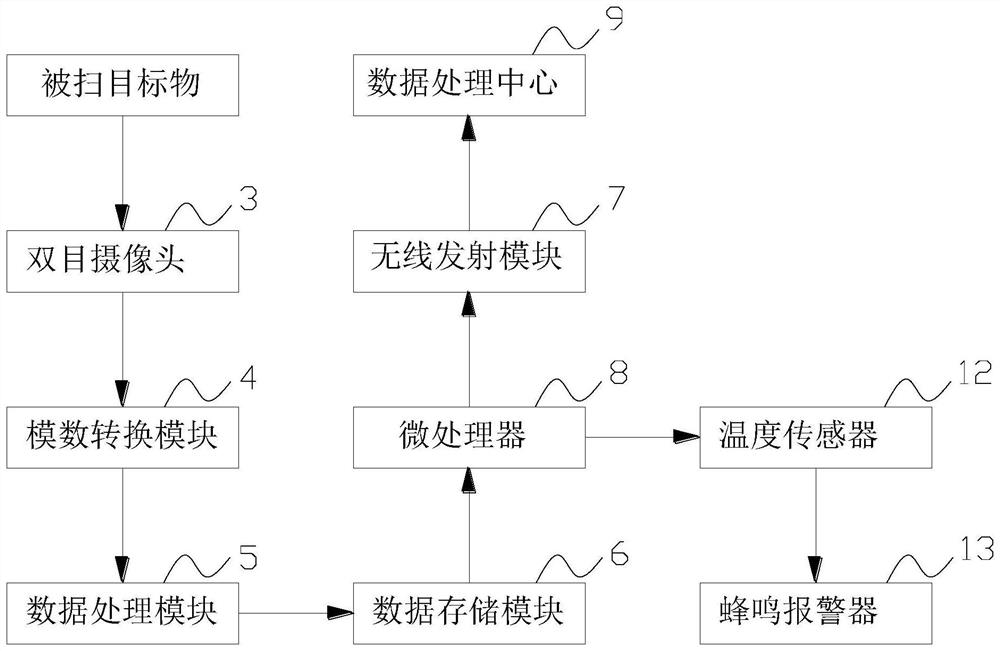
[0028] A binocular vision three-dimensional scanning system, please refer to the appendix figure 1 -Attached figure 2 As shown, it includes a scanner and a data processing center 9. The scanner includes a first casing 1 and a second casing 2. The second casing 2 is provided at the rear end of the first casing 1 and is connected with the first casing 1. The housing is formed in one piece, the first housing 1 is provided with a binocular camera 3, and the second housing 2 is provided with an analog-to-digital conversion module 4, a data processing module 5, a data storage module 6, a wireless transmission module 7 and a microprocessor 8, the binocular camera 3 is electrically connected with the analog-to-digital conversion module 4, the data processing module 5 is electrically connected with the analog-to-digital conversion module 4 and the data storage module 6 respectively, and the microprocessor 8 is respectively connected with the wireless transmission module 7 is electric...

Embodiment 2

[0039] The data processing center 9 performs feature extraction (FEM), disparity initialization (DIM), and disparity refinement (DIM) on the received data, wherein FEM provides robust multi-scale features for DIM and DRM, and DIM uses in low-resolution levels A 3D convolutional neural network initializes disparity, and DRM uses a multi-branch fusion (MBF) module at multiple scales to progressively recover disparity map details.

[0040] Further, FEM adopts L group convolution to reduce the spatial resolution, and its structure is as follows image 3 As shown, the L groups of convolutions are denoted as FEM-l (l=1, 2, ..., L), which both contain two convolution layers with a kernel size of 3, and the convolution strides are 2 and 1, respectively. Represents image features output by FEM at multiple resolution levels. In order to ensure the operating efficiency of the algorithm and fuse multi-scale features at the same time, the SPP (spatial pyramid pooling) layer is introduced ...


PUM


Abstract

The invention discloses a binocular vision three-dimensional scanning system. The binocular vision three-dimensional scanning system comprises a scanner and a data processing center. The scanner comprises a first shell and a second shell. The second shell is arranged at the rear end of the first shell and integrally formed with the first shell. A binocular camera is arranged in the first shell. Ananalog-digital conversion module, a data processing module, a data storage module, a wireless transmitting module and a microprocessor are arranged in the second shell. The binocular camera is electrically connected with the analog-digital conversion module. The data processing module is electrically connected with the analog-digital conversion module and the data storage module. The microprocessor is electrically connected with the wireless transmitting module and the data storage module. The data processing center is wirelessly connected to the scanner and constructs three-dimensional images collected by the scanner. According to the binocular vision three-dimensional scanning system, shooting and constructing are carried out at the same time, forming is rapid, the real-time effect is good, the scanner is convenient to carry, a wireless transmitting mode is adopted to exchange information with the data processing center, the use distance and range of the scanner are greatly improved, space is saved, and use is convenient.

Description

technical field [0001] The invention relates to the field of three-dimensional scanning, in particular to a binocular vision three-dimensional scanning system. Background technique [0002] 3D scanning refers to a high-tech integrating optical, mechanical, electrical and computer technologies. It is mainly used to scan the spatial shape, structure and color of an object to obtain the spatial coordinates of the surface of the object. The existing 3D scanners are basically One-piece structure, the scanner needs to be moved back and forth when scanning objects, which is cumbersome and has certain limitations in use. SUMMARY OF THE INVENTION [0003] The purpose of the present invention is to overcome the deficiencies of the prior art and provide a binocular vision three-dimensional scanning system to solve the problems raised in the above technical background. [0004] The purpose of this invention is to realize through the following technical solutions: [0005] A binocula...

Claims


Application Information

Patent Timeline
Patent Type & Authority Applications(China)
IPC IPC(8): G01B11/00G01K13/00G01K1/02G06T17/00G06T7/593
CPCG01B11/002G01K1/024G01K13/00G06T17/00G06T2200/08G06T2207/10012G06T2207/20081G06T2207/20084G06T7/593
Inventor 王巍
Owner JIMEI UNIV
Learn More