Balanced type optical fiber array biochemical spectrum light splitting device
A technology of optical fiber array and spectroscopic device, which is applied in the fields of biochemical analysis instruments and biochemical detection, can solve the problems of not being able to detect multiple wavelengths at the same time, reduce the accuracy of wavelengths, and fail to solve the problems of multi-wavelength detection, so as to improve the accuracy and stability of the results, Reduce product cost and reduce the effect of stray light interference
- Summary
- Abstract
- Description
- Claims
- Application Information
AI Technical Summary
Problems solved by technology
Method used
Image

Examples
Embodiment 1
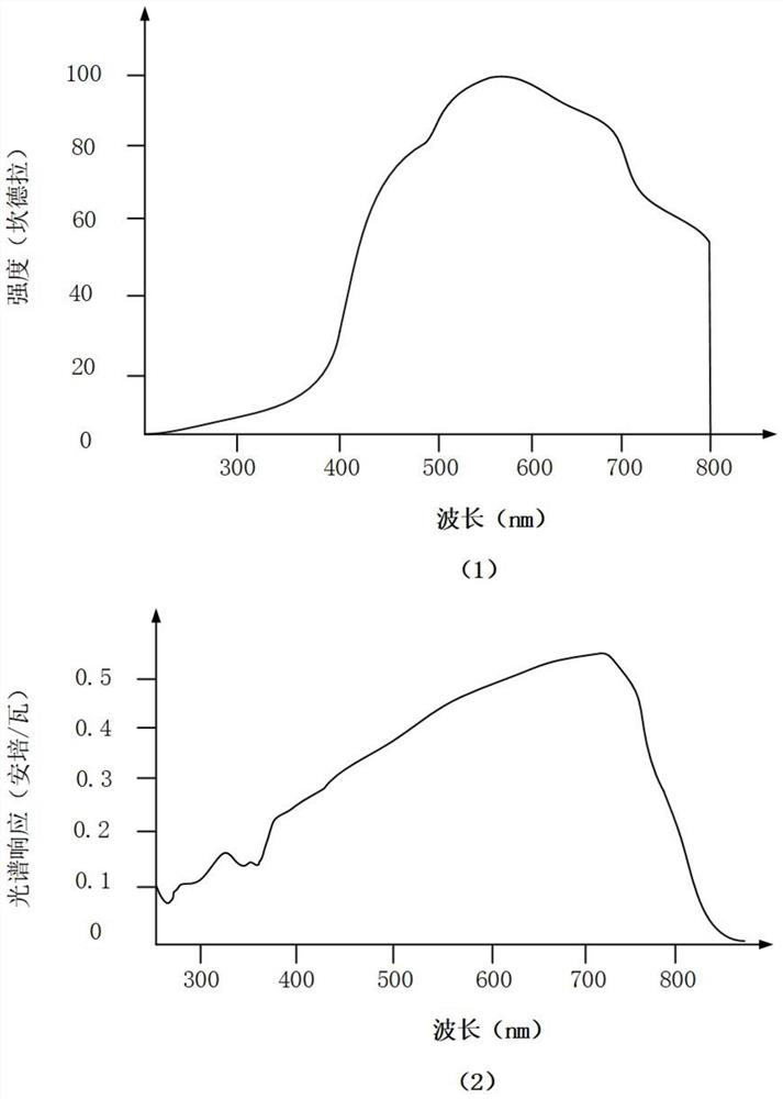
[0039]The ultraviolet light with a wavelength of 340 nm is often used in the detection items of the biochemical analyzer, so there are special requirements for the ultraviolet light emission of the light source 7. The ultraviolet light emitted by ordinary bulbs is quite weak, so we choose halogen lamps. The working wavelength of the halogen lamp is generally 325nm-800nm, which can meet the detection of biochemical analyzer from ultraviolet light to visible light. Moreover, halogen lamps have the advantages of strong light, long service life, high luminous efficiency and small size. The wavelength range that the present invention needs to split is 340nm-800nm,figure 1 To illustrate, (1) is the spectrum diagram of the halogen lamp used in this invention, and (2) is the schematic diagram of the spectral response range of the array-distributed silicon photocell detector 2. It can detect light with wavelengths of 340nm-800nm and is suitable for this invention. invention.
[0040]Due to th...
Embodiment 2
[0044]Such asFigure 4 As shown, a balanced optical fiber array biochemical spectroscopy device is composed of a light source 7, a sample cell 6, an optical fiber bundle receiving end 5, an optical fiber bundle output end 3, and a detector 2. The optical fiber receiving end 5 is inserted into the fixed sample cell 6 Insert the fiber bundle output end 3 into the detector 2 with its center facing the beam passing through the sample. The fiber bundle receiving end 5, the fiber bundle output end 3, and the detector 2 are plug-in types, using screw nuts 4 Install it.
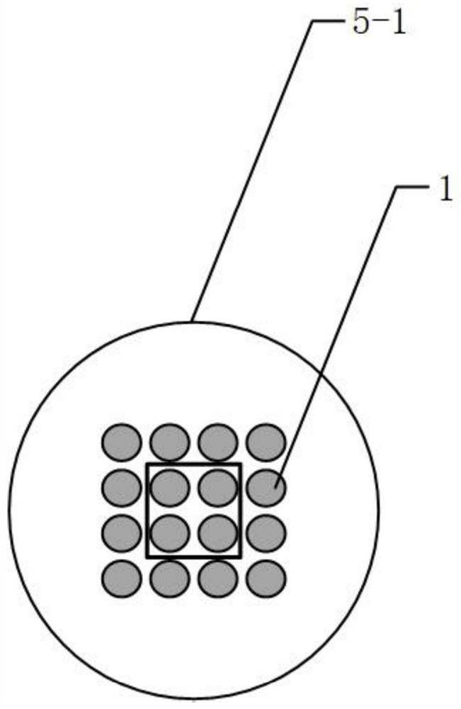
[0045]Figure 5 It is the internal schematic diagram of the fiber bundle receiving end 5 and the fiber bundle output end 3. The fiber 1 in the fiber bundle receiving end 5 is a 4×4, 16-hole square array, and the fiber bundle output end 3 adopts a straight line arrangement. The end face of each optical fiber at the output end is coated with interference filter film 3-1 with different parameters, and the half bandwidth is less th...
Embodiment 3
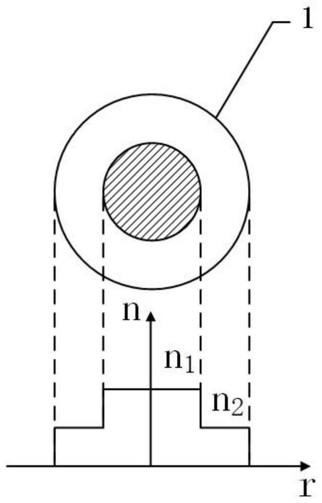
[0047]Such asFigure 5 As shown, in order to keep the refractive index of the fiber bundle 5-1 unaffected, the fiber bundle receiving end 5 is packaged with a low refractive index, fluorine-doped 4×4 square array distributed 16-hole quartz sleeve 5-2, where, The distribution of the quartz sleeve 5-2 is consistent with the distribution of the receiving end 5 of the optical fiber bundle.
[0048]Figure 6 It is a schematic diagram of the output end structure of the balanced fiber array biochemical spectroscopy device. Insert each optical fiber into the ceramic ferrule 2-1, fix it with glue, and grind the end surface to make it flat. Due to the needs of light splitting, the end surface of each optical fiber in the optical fiber bundle 5-1 is coated with an interference filter film 3 with different parameters. -1, the half bandwidth is less than or equal to 6nm, and then each ceramic ferrule 2-1 is arranged linearly and fixed inside a plug.
[0049]Such asFigure 7As shown, the detector 2 is a p...
PUM
 Abstract
Description
Claims
Application Information