Circular lithium battery and production method thereof

A lithium battery, circular technology, applied in the field of circular lithium batteries, can solve the problems of complex preparation and installation process, affect the effect of current extraction, reduce the welding area, etc., to improve the yield rate, save the liquid injection hole sealing process, Guarantee the effect of overcurrent capability

Pending Publication Date: 2020-12-29
星恒电源(滁州)有限公司
View PDF3 Cites 19 Cited by
  • Summary
  • Abstract
  • Description
  • Claims
  • Application Information

AI Technical Summary

Problems solved by technology

If this structure is applied to the negative battery cover plate, there will be the following problems: the disc cover and the current collecting plate are positioned through multiple positioning posts, thus resulting in isolation between the multiple fan-shaped areas of the current collecting plate and the battery cells by the disc cover , the collector plate can only be welded to the tab through several welding grooves, although the radial welding range is increased, but the circumferential welding area is reduced, which affects the current extraction effect
In this technical solution, the positive pole is set in the center of the cover plate, and explosion-proof valves and liquid injection holes are respectively set on both sides, and the positive pole piece of the battery is connected through the connecting piece. Although the safety performance of the battery is improved through the setting of the explosion-proof valve, but From the perspective of the overall structure, there are the following defects: (1) The explosion-proof valve and the liquid injection hole are respectively arranged on both sides of the cover plate, and there are multiple sealing points on the cover plate, so the preparation and installation process is relatively complicated; (2) Due to the The pole piece group adopts a vertical winding structure, the center of the winding is a through hole, and the liquid injection hole is located on the side of the cover plate, which will affect the liquid injection speed

Method used


Image

  • Circular lithium battery and production method thereof
  • Circular lithium battery and production method thereof
  • Circular lithium battery and production method thereof

Examples


Embodiment 1

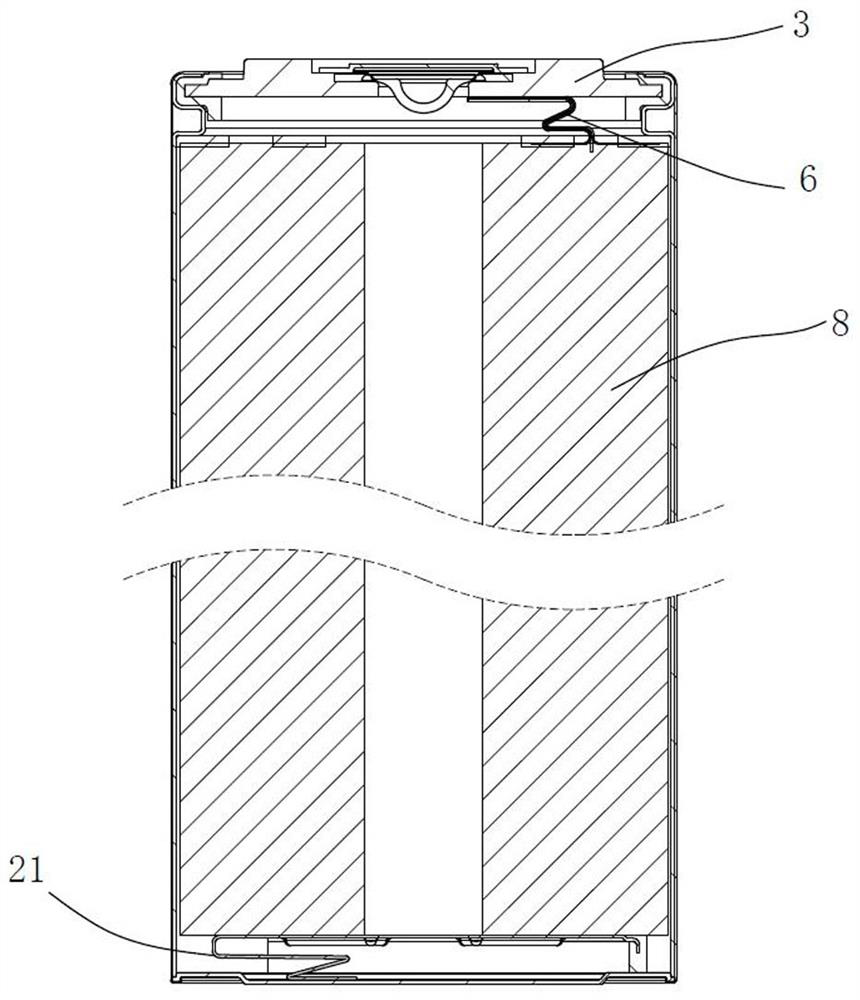
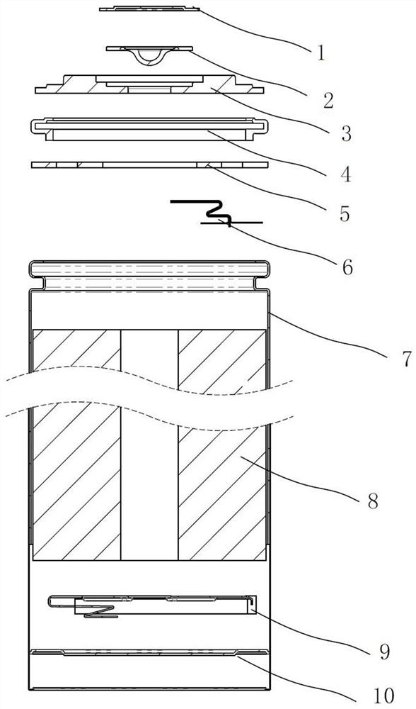
[0050] Embodiment 1: see attached figure 1 to attach image 3 As shown, a circular lithium battery includes a casing 7, a cell 8, a positive battery cover assembly and a negative battery cover assembly. The shell 7 adopts a stainless steel round tube, and the electric core 8 is located inside the shell 7 .

[0051] see Figure 4 with Figure 5 The electric core 8 includes a positive electrode foil 11, a negative electrode foil 12 and a separator 13, and the positive electrode foil 11 and the negative electrode foil 12 are separated by the separator 13 and wound into a cylindrical shape; A positive pole tab 6, an insulating gasket 5 is provided between the battery cell 8 and the positive battery cover plate assembly; the lower end of the battery cell is not aligned, and the order from short to long is the positive electrode foil 11, the separator 13, and the negative electrode foil. 12. The extended part of the negative electrode foil 12 is pressed and covered on the lower ...


PUM


Abstract

The invention discloses a circular lithium battery and a production method thereof. The lithium battery comprises a shell, a battery cell, a positive electrode battery cover plate assembly and a negative electrode battery cover plate assembly. A positive electrode foil and a negative electrode foil are separated by a diaphragm and then wound into a cylindrical battery cell. A positive electrode isa multi-tab structure, and a negative electrode is a full-tab structure. A sealing body is fixed on the anode battery cover plate in surrounding manner, and a safety valve is arranged in the middle.The negative electrode battery cover plate assembly comprises a current collector, a negative electrode battery cover plate and a current collector bracket; and the current collector body is fixedly connected to the upper part of the current collector bracket and is electrically connected with the negative electrode battery cover plate through a current collector connecting part. According to theinvention, an over-current capability of the battery is ensured, liquid injection and formation of the battery are facilitated, and installation is convenient and reliable.

Description

technical field [0001] The invention relates to a lithium ion battery, in particular to a cylindrical lithium ion battery and a preparation method thereof, and in particular to a circular lithium battery suitable for power batteries. Background technique [0002] With the continuous development of the new energy industry, lithium-ion batteries are used in various electric vehicles. Due to the large discharge current of the power battery, the internal electrolyte gas will increase the internal pressure during use, which is more likely to cause safety hazards. In order to reduce the heat generated during the use of the battery, in terms of the electrode lead-out method, the lead-out method of all tabs has appeared. The positive electrode foil and the negative electrode foil are respectively extended at the upper and lower ends of the battery to form a full tab. After kneading and flattening, it is welded on the current collector to reduce the resistance and heat generation at...

Claims


Application Information

Patent Timeline
Patent Type & Authority Applications(China)
IPC IPC(8): H01M2/26H01M2/30H01M2/36H01M2/04H01M2/08H01M2/10H01M2/12H01M10/04H01M10/0525H01M10/0583
CPCH01M10/0525H01M10/0583H01M10/0422H01M2220/20Y02E60/10Y02P70/50H01M50/107H01M50/186H01M50/655H01M50/538H01M50/152H01M50/533H01M50/3425H01M50/184H01M50/119H01M50/536H01M10/0431H01M10/049H01M10/0587
Inventor 王正伟丁坤钱建峰刘付召
Owner 星恒电源(滁州)有限公司
Why Eureka
Try Eureka