
Industrial robot automatic drilling system and using method

An industrial robot, robot technology, applied in boring/drilling, drilling/drilling equipment, manipulators, etc., can solve the problems of high processing cost of large drilling machines, low hole processing accuracy, long processing cycle, etc. Low, high yield, the effect of increasing the processing range

Inactive Publication Date: 2021-01-01
蒙美兰
View PDF9 Cites 2 Cited by
  • Summary
  • Abstract
  • Description
  • Claims
  • Application Information

AI Technical Summary

Problems solved by technology

[0006] The invention provides an automatic drilling system for industrial robots and its use method, which solves the problem of large-scale parts drilling in the prior art and the high processing cost of large drilling machines; relying on manual drilling, the hole processing accuracy is low and the reject rate is high. , The problem of long processing cycle

Method used


Image

  • Industrial robot automatic drilling system and using method
  • Industrial robot automatic drilling system and using method
  • Industrial robot automatic drilling system and using method

Examples


Embodiment 1

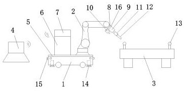
[0029]An industrial robot automated drilling system, seefigure 1 , Including automatic guided car 1, industrial robot 2, processing platform 3 and data processing platform 4. The automatic guided car 1 is equipped with a bottom plate 5 on the top, the top right side of the bottom plate 5 is installed with an industrial robot 2, and the top left side of the bottom plate 5 is installed The robot controller 6 is equipped with a PLC controller 7 on the top of the robot controller 6; a connecting board 8 is installed at the end of the sixth axis of the industrial robot 2, and the connecting board 8 is installed with a motor 9 and a camera 10 respectively. The output terminal of the motor 9 is connected with One end of the chuck 11 is connected, and the other end of the chuck 11 clamps the drill bit 12; the PLC controller 7 is respectively connected with the automatic guided car 1, the robot controller 6, the motor 9 and the camera 10 through cables; the data processing platform 4 is cont...

Embodiment 2

[0032]An industrial robot automated drilling system, seefigure 1 , Similar to Embodiment 1, the difference is that four supporting legs 14 are installed at the bottom of the automatic guided vehicle 1, and the four supporting legs 14 are distributed at the four corners of the automatic guided vehicle 1. When the automatic guided vehicle 1 stops, The four supporting legs 14 push up the automatic guiding cart 1 and the supporting legs 14 make the automatic guiding cart 1 more stable when it stops at the processing position.

[0033]It may be further that the bottom surface of the support leg 14 is provided with horizontal and vertical anti-skid patterns to improve the friction with the ground.

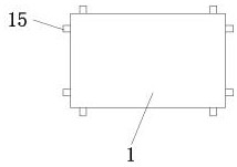
[0034]It can go further, seefigure 2 The four sides of the automatic guided vehicle 1 are respectively installed with distance sensors 15 which detect that a person is approaching, and the industrial robot 2 automatically stops moving to protect the safety of the persons.

[0035]It can be further that...

Embodiment 3

[0052]The use method of an industrial robot automated drilling system as described in embodiments 1 and 2, includes the following steps:

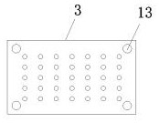
[0053]In the first step, the workpiece with clamping tooling is fixed on the processing platform 3, and the positional relationship between the reference ball 13 and the workpiece is fixed;

[0054]The second step is to correct the positional relationship between the industrial robot 2 and the camera 10 and the drill bit 12;

[0055]In the third step, the reference ball 13 is measured by the camera 10, and the coordinate system of the industrial robot 2, the camera 10, the drill bit 12 and the reference ball 13 are unified on the data processing platform 4 to obtain the positional relationship between the drill bit 12 and the workpiece;

[0056]In the fourth step, the drill bit 12 starts to drill holes on the workpiece.


PUM


Abstract

The invention discloses an industrial robot automatic drilling system and a using method. The industrial robot automatic drilling system comprises an automatic guiding trolley, an industrial robot, amachining platform and a data processing platform, wherein a bottom plate is installed at the top of the automatic guiding trolley, and the industrial robot is installed on the right side of the top of the bottom plate; a connecting plate is installed at the tail end of a sixth shaft of the industrial robot, a motor and a camera are installed on the connecting plate, the output end of the motor isconnected with one end of a chuck, and the other end of the chuck clamps a drill bit; the data processing platform is connected with a PLC in a wireless control mode; and at least four reference balls are installed on the side edge of the top of the machining platform. The automatic guiding trolley drives the industrial robot to move, the drilling range is enlarged, and flexible machining is achieved; and the reference balls are measured at different positions through the camera, the position relation between the drill bit and a workpiece is calibrated, it is guaranteed that when the robot islocated at different positions, the drill bit and the workpiece are located in a unified coordinate system, the workpiece drilling machining precision is guaranteed, the efficiency is high, the yieldis high, and the cost is low.

Description

Technical field[0001]The invention belongs to the technical field of mechanical processing, and particularly relates to an industrial robot automated drilling system and a use method.Background technique[0002]Drilling machine refers to a machine tool that mainly uses a drill to make holes on a workpiece. Usually, the rotation of the drill is the main movement, and the axial movement of the drill is the feed movement. The drilling machine can drill through holes and blind holes, change special tools, expand, counter-hole, ream or tapping and other processing. During processing, the workpiece does not move, let the tool move, align the tool center with the hole center, and make the tool rotate.[0003]In the early 1970s, drilling machines were still controlled by ordinary relays in the world. In the late 1980s, due to the emergence of numerical control technology, they gradually began to be applied to drilling machines, and this advanced technology was promoted especially after 90 years...

Claims


Application Information

Patent Timeline
Patent Type & Authority Applications(China)
IPC IPC(8): B23B39/00B23B47/00B25J11/00
CPCB23B39/00B23B47/00B25J11/005B25J11/0055
Inventor 蒙美兰
Owner 蒙美兰
Learn More