
Conveyor belt achieving waste sorting

A conveyor belt and waste technology, which is applied to conveyors, conveyor objects, transportation and packaging, etc., can solve the problems of manual operation, safety, hidden dangers, and the inability of robots to fully identify and grasp, so as to achieve simple device design and improve The effect of high efficiency and operation reliability

Pending Publication Date: 2021-01-01
苏州岳邦汽车科技有限公司
View PDF0 Cites 0 Cited by
  • Summary
  • Abstract
  • Description
  • Claims
  • Application Information

AI Technical Summary

Problems solved by technology

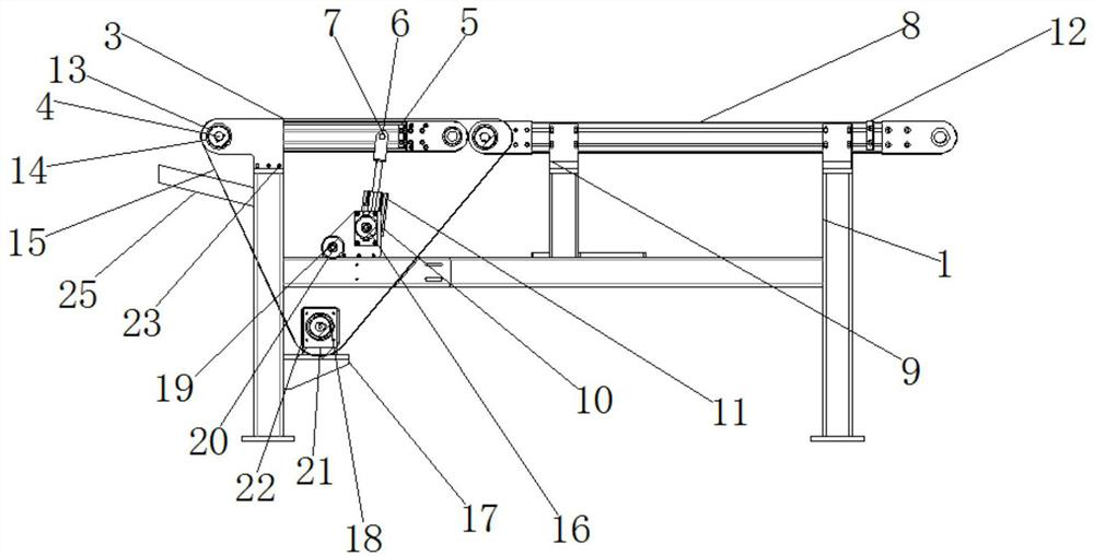
[0004] The object of the present invention is to provide a conveyor belt to realize waste sorting, to solve the above-mentioned background technology. In the traditional laser blanking line equipment, when the laser cutting machine cuts the sheet, the sheet is still on the cutting table, and the cutting head walks. Cutting track, so as to cut out the required shape. After the cutting is completed, the finished products and waste materials stay on the cutting table, and the waste materials can be taken out manually or by a robot device, and then the finished products can be transported to the next process. Due to the different shapes and sizes of waste materials, The manipulator cannot fully identify and grasp, which requires more manual intervention and even requires a special person to be responsible for manual grasping. The production line has to be suspended and waiting, and there are many safety hazards in manual operations, which is a major drawback of this type of production line.

Method used


Image

  • Conveyor belt achieving waste sorting
  • Conveyor belt achieving waste sorting
  • Conveyor belt achieving waste sorting

Examples


Embodiment Construction

[0020] The following will clearly and completely describe the technical solutions in the embodiments of the present invention with reference to the drawings in the embodiments of the present invention.

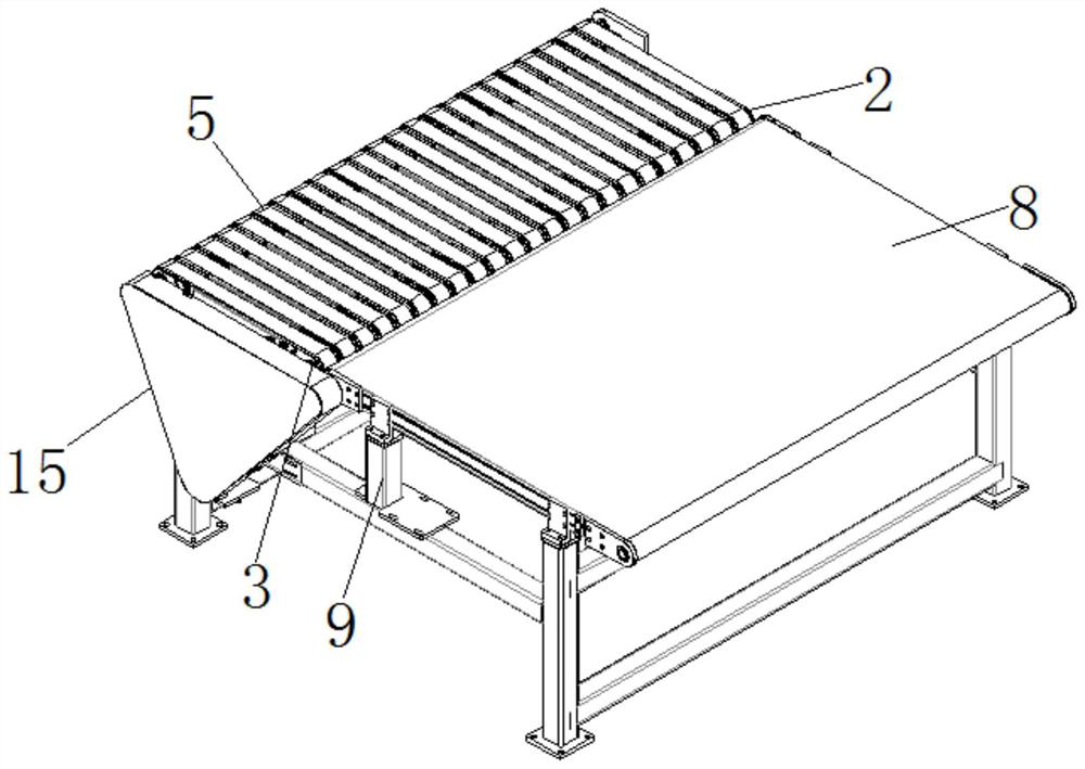
[0021] like Figure 1-3 As shown, the present invention provides a technical solution: the conveyor belt realizes waste sorting, including a frame 1, the top end of the frame 1 is rotatably connected with a belt drive shaft 4, and the outer wall of the belt drive shaft 4 is connected with a first Belt set 5, a U-shaped plate 6 is installed below the first belt set 5, a second belt set 8 is installed on one side of the first belt set 5, and a fixed block 10 is installed below the U-shaped plate 6, so A cylinder 11 is installed on the inner wall of the fixed block 10, an adjustment block 12 is installed on the outer end of the second belt set 8, and a first synchronous pulley 14 is arranged on the outer side of the frame 1, and the first synchronous pulley 14 is connected with t...


PUM


Abstract

The invention discloses a conveying belt achieving waste sorting. The conveying belt comprises a rack. One end of the top of the rack is rotationally connected with a belt driving shaft, the outer wall of the belt driving shaft is in transmission connection with a first belt set, a U-shaped plate is installed below the first belt set, a second belt set is installed on one side of the first belt set, and a fixing block is installed below the U-shaped plate; and an air cylinder is installed on the inner wall of the fixing block, an adjusting block is installed at the end of the outer side of thesecond belt set, a first synchronous belt wheel is arranged on the outer side of the rack, the first synchronous belt wheel is connected with the belt driving shaft in an inserted manner, a synchronous belt tensioning wheel is installed on the outer wall of the fixing block, a second synchronous belt wheel is installed below the first synchronous belt wheel, and one side of the synchronous belt tensioning wheel is rotationally connected with a fixing tensioning wheel axle. The whole production process is free of manual intervention, an operator only carries out database parameter calling andproduction monitoring outside a production line, and automatic production of a system is achieved, and high efficiency and safety are achieved.

Description

technical field [0001] The invention relates to the technical field of laser cutting, in particular to realizing waste sorting on conveyor belts. Background technique [0002] Laser cutting is the use of a focused high-power-density laser beam to irradiate the workpiece, so that the irradiated material is rapidly melted, vaporized, ablated or reached the ignition point, and at the same time the molten material is blown away by the high-speed airflow coaxial with the beam, so as to realize the cutting of the workpiece. open. Laser cutting is one of the thermal cutting methods. [0003] In the traditional laser blanking line equipment, when the laser cutting machine is cutting the sheet, the sheet is still on the cutting table, and the cutting head walks the cutting track to cut out the required shape. After the cutting is completed, the finished product and waste remain On the cutting table, waste materials are taken out manually or by a robot device before the finished pro...

Claims


Application Information

Patent Timeline
Patent Type & Authority Applications(China)
IPC IPC(8): B23K26/70B65G15/12B65G23/44B65G47/74
CPCB65G15/12B65G23/44B65G47/74B23K26/702
Inventor 戴秋连保琳
Owner 苏州岳邦汽车科技有限公司
Learn More