Catalyst in-situ preparation device for flow battery and catalyst preparation method

A flow battery, in-situ preparation technology, applied in fuel cells, battery electrodes, electrochemical generators, etc., can solve problems such as scarcity of research, achieve uniform distribution, reduce flow resistance, and improve uniformity.

Pending Publication Date: 2021-01-01
SOUTHWEST JIAOTONG UNIV
View PDF0 Cites 3 Cited by
  • Summary
  • Abstract
  • Description
  • Claims
  • Application Information

AI Technical Summary

Problems solved by technology

However, studies on this in situ platin

Method used


Image

  • Catalyst in-situ preparation device for flow battery and catalyst preparation method

Examples


Embodiment 1

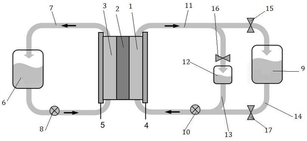
[0027] Such as figure 1 As shown, the single cell area of ​​the all-vanadium redox flow battery is 30x 50cm 2150L of electrolyte is stored in the positive and negative liquid storage tanks, and the vanadium ion concentration is 1.5M / L. The storage tank of the bypass plating solution is only 1.0L, and the concentration of bismuth chloride is 8mM / L. During electroplating, valve 16 is opened, valves 15 and 17 are closed, and the negative electrode of the vanadium battery is switched to the electroplating bypass. During electroplating, the flow rate is 3L / min, and the electroplating current density used is 10mA cm -2 , the electroplating process works for 1 second, rests for 2 seconds, and uses this as a cycle for 60 cycles, and then uses a constant current of 3mA cm -2 Electroplating was performed to direct the complete consumption of bismuth ions. After the electroplating is completed, close the valve 16, open the valves 15 and 17, and the battery is charged and discharged n...

Embodiment 2

[0029] Such as figure 1 As shown, the all-vanadium redox flow battery stack, 3 layers of single cells are connected in series, and the area of ​​each single cell is 30x50cm 2 , the positive and negative liquid storage tanks each store 250L electrolyte, in which the concentration of vanadium ions is 1.5M / L. The bypass electroplating solution storage tank is only 1.5L, and the concentration of bismuth chloride is 14mM / L. During electroplating, valve 16 is opened, valves 15 and 17 are closed, and the negative electrode of the vanadium battery is switched to the electroplating bypass. During electroplating, the flow rate is 8L / min, and the electroplating current density used is 8mA cm -2 , the electroplating process works for 0.5 seconds, rests for 1 second, and uses this as a cycle for 100 cycles, and then conducts electroplating with a constant current of 2mA cm-2 to guide the complete consumption of bismuth ions. After the electroplating is completed, close the valve 16, ope...

Embodiment 3

[0031] Such as figure 1 As shown, the all-vanadium redox flow battery stack, 3 layers of single cells are connected in series, and the area of ​​each single cell is 30x50cm 2 , the positive and negative liquid storage tanks each store 250L electrolyte, in which the concentration of vanadium ions is 1.5M / L. The bypass electroplating solution storage tank is only 1.5L, and the concentration of bismuth chloride is 2mM / L. During electroplating, valve 16 is opened, valves 15 and 17 are closed, and the negative electrode of the vanadium battery is switched to the electroplating bypass. During electroplating, the flow rate is 8L / min, and the electroplating current density used is 5mA cm -2 , the electroplating process works for 0.1 second, rests for 1 second, and uses this as a cycle for 100 cycles, and then conducts electroplating with a constant current of 2mA cm-2 to guide the complete consumption of bismuth ions. After the electroplating is completed, close the valve 16, open ...


PUM


Abstract

The present invention discloses a catalyst in-situ preparation device for a flow battery and catalyst preparation method. The catalyst in-situ preparation device comprises a positive electrode half battery and a negative electrode half battery, and in-situ electroplating of a catalyst can be carried out before charging and discharging of the flow battery through an electroplating bypass, an electroplating liquid storage tank and electroplating liquid which are arranged on one side of the negative electrode half battery; or after the flow battery is charged and discharged for a certain time andthe morphology of the catalyst is changed, the in-situ electroplating process is carried out again, and the ion concentration of the catalyst precursor ions in the electroplating liquid is improved by arranging the electroplating bypass, the electroplating liquid storage tank and the electroplating liquid, so that the catalyst is mroe uniformly distributed at the negative electrode of the flow battery. The catalyst electroplating preparation method of intermittent electroplating is utilized, so that catalyst particles are smaller, the particle density and the uniformity are higher, and the problems that an existing catalyst is uneven in distribution and blocks a porous electrode are solved.

Description

technical field [0001] The invention belongs to the field of large-scale energy storage, and in particular relates to a device for in-situ preparation of a liquid flow battery catalyst and a catalyst preparation method. Background technique [0002] Flow battery is an advanced electrochemical power storage technology. According to the positive and negative active materials used, it can be divided into: all-vanadium, all-lead, sulfur-bromine, zinc-bromine, iron-chromium flow batteries, etc. For the preparation of catalysts for flow batteries, a common method is to add catalyst precursor ions, such as bismuth ions or indium ions, to the electrolyte after the battery is assembled, and then directly deposit the catalyst metal bismuth Or indium is directly electroplated to the negative electrode of the flow battery. Compared with the traditional scheme of loading the catalyst on the electrode in advance, this in-situ electroplating catalyst scheme has the advantage of simple ope...

Claims


Application Information

Patent Timeline
IPC IPC(8): H01M4/88H01M8/18H01M8/2465C25D21/00C25D5/18
CPCC25D5/18C25D21/00H01M4/8853H01M8/188H01M8/2465Y02E60/50
Inventor 曾义凯
Owner SOUTHWEST JIAOTONG UNIV
Why Eureka
Try Eureka