Microbial fuel cell wastewater treatment system

A wastewater treatment system and fuel cell technology, which is applied in the fields of biochemical fuel cells, biological water/sewage treatment, textile industry wastewater treatment, etc. The effect of mass transfer efficiency, saving membrane cost and improving treatment effect

Pending Publication Date: 2021-01-08
张家港市杨舍丝印工艺厂
View PDF0 Cites 2 Cited by
  • Summary
  • Abstract
  • Description
  • Claims
  • Application Information

AI Technical Summary

Problems solved by technology

[0003] Due to the low power generation voltage of MFC in the existing wastewater treatment process, usually 250-400mV, it is difficult to fully recycle and utilize electric energy. At the same time, when the wastewater contains refractory organic matter, there are problems such as long start-up period and low success rate.

Method used


Image

  • Microbial fuel cell wastewater treatment system

Examples


Embodiment 1

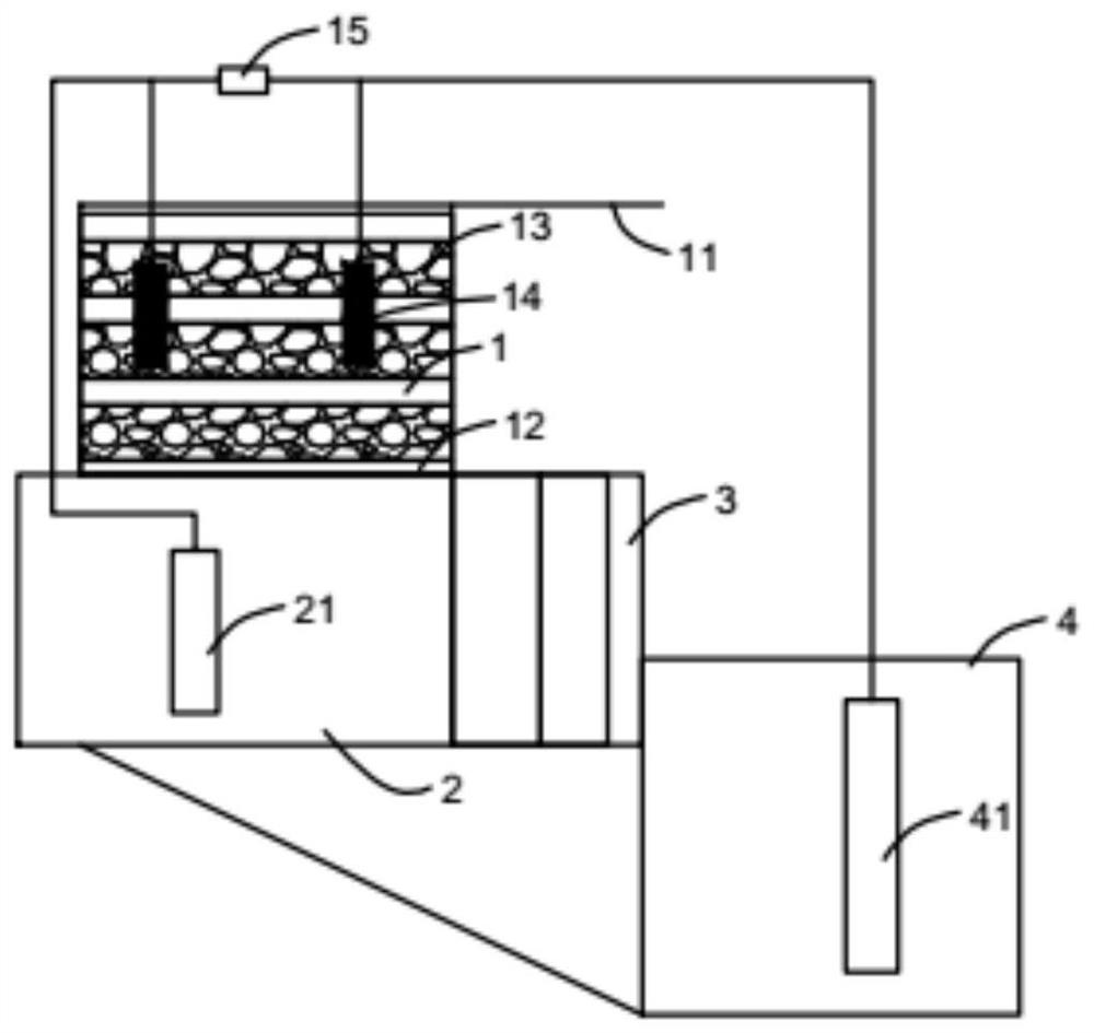
[0028] like figure 1 Shown, a kind of microbial fuel cell waste water treatment system comprises: Comprising: iron-carbon pool 1, cathode room 2, iron-carbon reduction pool 3, anode room 4, described iron-carbon pool 1 top is provided with water inlet pipe 11, and described iron-carbon pool 1 An aeration device 12 is arranged at the bottom of the carbon pool 1, and a multi-layer iron-carbon filler layer 13 is arranged in the iron-carbon pool, and a gap is arranged between the iron-carbon filler layers; the iron-carbon pool 1 communicates with the cathode chamber 2, and the A cathode 21 is arranged in the cathode chamber 2, and the cathode chamber 2 communicates with the iron-carbon reduction pool 3, and an iron-carbon filler is arranged in the iron-carbon reduction pool 3, and is added to the iron-carbon reduction pool during the wastewater treatment process. Reductant, the iron-carbon reduction pool 3 communicates with the anode chamber 4, an anode 41 is set in the anode cham...

Embodiment 2

[0032] A printing and dyeing wastewater CODcr is 890mg / L, BOD5 is 256mg / L.

[0033] The invention discloses a microbial fuel cell waste water treatment system, comprising: an iron-carbon pool 1, a cathode chamber 2, an iron-carbon reduction pool 3, and an anode chamber 4; a water inlet pipe 11 is arranged above the iron-carbon pool 1; An aeration device 12 is arranged at the bottom of the pool 1, and a multi-layer iron-carbon filler layer 13 is arranged in the iron-carbon pool, and a gap is arranged between the iron-carbon filler layers; the iron-carbon pool 1 communicates with the cathode chamber 2, and the cathode A cathode 21 is arranged in the chamber 2, and the cathode chamber 2 is connected to the iron-carbon reduction pool 3, and an iron-carbon filler is arranged in the iron-carbon reduction pool 3, and a reduction agent is added to the iron-carbon reduction pool during the wastewater treatment process. agent, the iron-carbon reduction pool 3 communicates with the anode...


PUM

PropertyMeasurementUnit
electrical resistanceaaaaaaaaaa
current efficiencyaaaaaaaaaa

Abstract

The invention discloses a microbial fuel cell wastewater treatment system which comprises an iron-carbon pool, a cathode chamber, an iron-carbon reduction pool and an anode chamber, a water inlet pipeis arranged above the iron-carbon pool, an aeration device is arranged at the bottom of the iron-carbon pool, multiple iron-carbon filler layers are arranged in the iron-carbon pool, and gaps are formed between the iron-carbon filler layers; wherein the iron-carbon pool is communicated with the cathode chamber, a cathode is arranged in the cathode chamber, the cathode chamber is communicated withthe iron-carbon reduction pool, iron-carbon filler is arranged in the iron-carbon reduction pool, a reducing agent is added into the iron-carbon reduction pool in the wastewater treatment process, the iron-carbon reduction pool is communicated with the anode chamber, and an anode is arranged in the anode chamber. And a load is arranged between the anode and the cathode.

Description

technical field [0001] The invention belongs to the field of wastewater treatment, and in particular relates to a microbial fuel cell wastewater treatment system. Background technique [0002] Microbial fuel cell (MFC) is a technology that uses the catalysis of microorganisms to convert chemical energy in organic matter into electrical energy. The basic principle is: in the anaerobic environment of the anode chamber, organic matter decomposes under the action of microorganisms and releases electrons and protons. A current is formed at the cathode, and protons are transferred to the cathode through the proton exchange membrane, and the oxidant (usually oxygen) obtains electrons at the cathode and is reduced and combined with protons to form water. The reaction chamber of traditional MFCs is usually divided into an anode chamber and a cathode chamber by a separation membrane. Microorganisms process wastewater in the anode chamber and generate electrons. The cathode chamber ge...

Claims


Application Information

Patent Timeline
Patent Type & Authority Applications(China)
IPC IPC(8): C02F3/00H01M8/16C02F101/30C02F103/06C02F103/30C02F103/34
CPCC02F3/005C02F2101/30C02F2103/06C02F2103/30C02F2103/343H01M8/16Y02E60/50
Inventor 戴积法戴强王诚
Owner 张家港市杨舍丝印工艺厂
Why Eureka
Try Eureka