Supercharge Your Innovation With Domain-Expert AI Agents!

Garbage incineration grate furnace based on circulating fluidized bed furnace body

A waste incinerator and circulating fluidized bed technology, applied in the direction of incinerator, combustion method, combustion type, etc., can solve the problems of not exceeding 3 months, affecting production efficiency and economic benefits, frequent maintenance, etc., to improve production Efficiency and economic benefits, improved continuous running time, effect of small modification workload

Pending Publication Date: 2021-01-08
CHINA WESTERN POWER INDAL
View PDF0 Cites 0 Cited by
  • Summary
  • Abstract
  • Description
  • Claims
  • Application Information

AI Technical Summary

Problems solved by technology

In the early days, circulating fluidized bed technology was the main technology, but because urban domestic waste contains a large amount of construction waste, stones, iron wires and other debris, when using circulating fluidized bed boilers for power generation, the waste needs to be crushed and screened before entering the furnace , otherwise, a series of problems may occur, such as blockage of the feeding port, wind caps wound by iron wires, and damage to the caps by stones, etc., which will affect the fluidization effect and the continuous and stable operation of the boiler, so the workload in the early stage is heavy; even so, with the running time Cumulatively, the air distribution plate is still unavoidably clogged and damaged. The continuous operation time of garbage incineration using circulating fluidized bed technology is generally about one month, and the longest is no more than 3 months. Frequent maintenance affects production efficiency and economic benefits

Method used


Image

  • Garbage incineration grate furnace based on circulating fluidized bed furnace body

Examples


Embodiment Construction

[0010] Below in conjunction with accompanying drawing, the present invention is described in further detail.

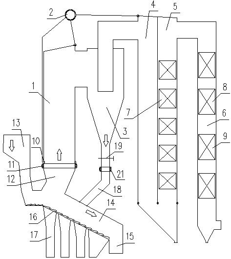
[0011] like figure 1 As shown, the waste incineration grate furnace based on the circulating fluidized bed furnace body of this embodiment includes a furnace 1, a drum 2, a cyclone separator 3, a first shaft flue 4, a second shaft flue 5, and a rear shaft Flue 6, superheater 7, economizer 8 and air preheater 9, the furnace is provided with a lower water-cooled wall header 10; There is an expansion joint 11 between them; one side of the incinerator 12 is connected with a feed port 13, and the other side is connected with a back arch 14 inclined downward from front to back. A pusher grate 16 is provided at the bottom of the feed opening 13 and the back arch 14, and several ash hoppers 17 are arranged under the back arch 14; Flap flap valve 19, expansion joint 21 is provided on return leg 18;

[0012] The present invention retains the circulating fluidized bed furnace...


PUM


Abstract

The invention discloses a garbage incineration grate furnace based on a circulating fluidized bed furnace body, which comprises a hearth, a boiler barrel, a cyclone separator, a first vertical shaft flue, a second vertical shaft flue, a tail vertical shaft flue, a superheater, a coal saver and an air preheater, wherein the hearth is provided with a lower water-cooled wall header; an incinerator isarranged below the hearth, and an expansion joint is arranged between the lower water-cooled wall header and the upper end of the incinerator; one side of the incinerator is connected to a feeding hole, and the other side of the incinerator is connected to a rear arch; the rear arch is connected to a slag discharge hole, a pushing fire grate is arranged at the bottom of the feeding hole and the bottom of the rear arch, and a plurality of ash buckets are arranged below the rear arch; and a material return leg of the cyclone separator is connected to the rear arch, and a flap valve is arrangedin the material return leg. The garbage incineration grate furnace has the advantages of being small in transformation workload and short in period, can directly feed garbage into the incinerator forcombustion without crushing and screening, can greatly improve continuous operation time of the incinerator, and improves production efficiency and economic benefits.

Description

technical field [0001] The invention relates to a waste incineration grate furnace based on a circulating fluidized bed furnace body. Background technique [0002] At present, waste incineration power generation technology is mainly divided into two schools: circulating fluidized bed technology and grate furnace technology. In the early days, circulating fluidized bed technology was the main technology, but because urban domestic waste contains a large amount of construction waste, stones, iron wires and other debris, when using circulating fluidized bed boilers for power generation, the waste needs to be crushed and screened before entering the furnace , otherwise, a series of problems may occur, such as blockage of the feeding port, wind caps wound by iron wires, and damage to the caps by stones, etc., which will affect the fluidization effect and the continuous and stable operation of the boiler, so the workload in the early stage is heavy; even so, with the running time ...

Claims


Application Information

Patent Timeline
IPC IPC(8): F23G5/30F23G5/44F23G5/46F23J15/02F22B31/08
CPCF22B31/0084F22B31/08F23G5/002F23G5/006F23G5/30F23G5/44F23G5/444F23G5/46F23G2203/105F23G2203/502F23G2206/203F23J15/027F23J2217/40Y02E20/12
Inventor 郝小波
Owner CHINA WESTERN POWER INDAL
Features
  • R&D
  • Intellectual Property
  • Life Sciences
  • Materials
  • Tech Scout
  • Unparalleled Data Quality
  • Higher Quality Content
  • 60% Fewer Hallucinations
Learn More