Thermal radiation type energy-saving and environment-friendly scrap steel preheating system

An energy-saving, environmental-friendly, heat-radiating technology, applied to preheating costs, lighting and heating equipment, furnaces, etc., can solve the problems of uneven heat conduction, difficult cleaning, and high equipment investment costs, so as to save consumption, improve heat utilization rate, The effect of shortening the smelting time

Pending Publication Date: 2021-01-08
HENAN TAIHANG QUANLI HEAVY IND
View PDF0 Cites 0 Cited by
  • Summary
  • Abstract
  • Description
  • Claims
  • Application Information

AI Technical Summary

Problems solved by technology

A large amount of high-temperature heat will be generated during scrap steel smelting. Due to the high temperature, the heat cannot meet the requirements of direct discharge. It needs to be cooled before being discharged. However, since the temperature of these flue gases can be as high as 1300 degrees, cooling on the one hand It needs to invest in cooling equipment. On the other hand, the cooling equipment takes up space and does not achieve good economic benefits. In order to recycle these high-temperature gases, the market has emerged the idea of ​​using this high temperature to preheat scrap steel to be smelted. Now There are two preheating methods in some cases, one is horizontal conveying preheating, and the second is vertical shaft preheating
[0003] Horizontal conveying preheating is to install a fume hood on the upper part of the conveyor belt, and reverse the heat flow from the output port of the conveying conveyor belt to the input port, so that the scrap steel can be preheated by the recovered heat flowing in the reverse direction during the scrap steel conveying process. However, there are certain problems in this preheating method, because the heat flows from the upper surface of the conveying scrap steel layer, and cannot be uniformly transferred to the bottom of the conveying material layer, resulting in uneven heat conduction and poor heat transfer effect.
[0004] Shaft preheating is directly installed on the upper part of the smelting electric furnace. Using the principle of upward flow of heat during smelting, the scrap steel in the upper shaft silo is preheated by the high-temperature flue gas flowing upward, because the flue gas can flow upward through the scrap steel layer , this method has a better preheating effect, but because the scrap steel weighs 20-30 tons, the shaft silo and the electric furnace located below are easily damaged by the scrap steel fed from above. To solve this problem, a support grate is added to the shaft It is used to pick up materials to prevent it from being smashed by scrap steel. Due to the unfixed shape of scrap steel, there are some relatively thin and thin shapes mixed in the scrap steel when it is recycled. Since the shaft directly passes through the melting furnace, it enters the shaft The temperature in the furnace is as high as 1300 degrees. These relatively thin and fine steel scraps will first melt and flow downward during preheating, thereby blocking the overheating holes supporting the grate, so that the heat cannot penetrate the scrap steel layer upwards from the supporting grate. Lost the function of preheating, at the same time, because the heat is concentrated in the shaft and cannot be discharged, once the heat accumulates to a certain pressure, it will cause an explosion, which will cause a safety accident and cause a very serious safety hazard. In addition, once the supporting grate is flowed It is difficult to clean up the blockage of molten steel, which leads to the scrapping of the supporting grate, which makes the equipment investment cost high and the equipment maintenance rate is too high

Method used


Image

  • Thermal radiation type energy-saving and environment-friendly scrap steel preheating system
  • Thermal radiation type energy-saving and environment-friendly scrap steel preheating system
  • Thermal radiation type energy-saving and environment-friendly scrap steel preheating system

Examples


Embodiment Construction

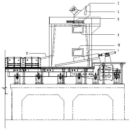
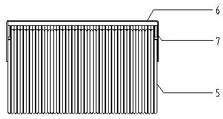
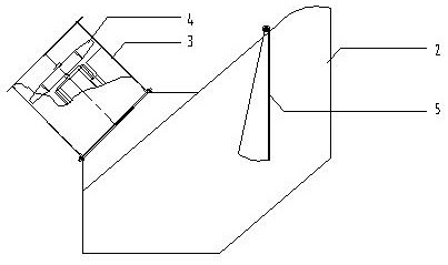
[0027] As shown in the attached figure, the thermal radiation energy-saving and environment-friendly scrap steel preheating system includes a horizontal preheating conveying mechanism and a vertical preheating conveying mechanism, and the vertical preheating conveying mechanism is connected with the horizontal preheating conveying mechanism. By setting the connected vertical preheating conveying mechanism and horizontal preheating conveying mechanism, the horizontal preheating conveying mechanism is connected with the melting electric furnace, and the high temperature gas generated during electric furnace smelting first flows backward through the horizontal preheating conveying mechanism, and then passes through the horizontal The preheating conveying mechanism enters into the vertical preheating conveying mechanism connected with the horizontal preheating conveying mechanism for preheating. By first entering the horizontal preheating conveying mechanism, the steel scrap enters...


PUM


Abstract

The invention discloses a thermal radiation type energy-saving and environment-friendly scrap steel preheating system. The system comprises a horizontal preheating conveying mechanism and a vertical preheating conveying mechanism, and the vertical preheating conveying mechanism is connected with the horizontal preheating conveying mechanism. The vertical preheating conveying mechanism comprises avertical shaft stock bin, a windproof system is arranged on the vertical shaft stock bin, and the windproof system comprises a windproof pipe, a material blocking mechanism, a dynamic sealing mechanism and a convection heating windproof mechanism. According to the system, the steel scrap preheating temperature is increased, the electricity consumption per ton of steel of an electric furnace is reduced, and the smelting time is shortened; and therefore, waste steel preheating is safe and stable, meanwhile, heat generated after smelting is recycled to the maximum extent, and the heat utilizationrate is greatly increased.

Description

technical field [0001] The invention relates to a scrap steel preheating system, in particular to a thermal radiation energy-saving and environment-friendly scrap steel preheating system. Background technique [0002] Scrap iron and steel resources are one of the indispensable resources in today's world iron and steel industry. According to the statistics of international authoritative professional organizations, in the past 50 years, 40% of the crude steel produced in the world is made of scrap steel. A large amount of high-temperature heat will be generated during scrap steel smelting. Due to the high temperature, the heat cannot meet the requirements of direct discharge. It needs to be cooled before being discharged. However, since the temperature of these flue gases can be as high as 1300 degrees, cooling on the one hand It needs to invest in cooling equipment. On the other hand, the cooling equipment takes up space and does not achieve good economic benefits. In order ...

Claims


Application Information

Patent Timeline
IPC IPC(8): F27D13/00
CPCF27D13/002
Inventor 黄恒黄全利杜光辉
Owner HENAN TAIHANG QUANLI HEAVY IND
Why Eureka
Try Eureka