A multi-level structure microchannel mixer and its fluid mixing method

A microchannel and mixer technology, applied in fluid mixers, chemical instruments and methods, mixers, etc., can solve problems such as easy clogging, installation and cleaning, difficult process control, complex flow patterns, etc., and achieve good mixing effect and intensified Fluid disturbance, the effect of increasing the fluid flow velocity

Active Publication Date: 2021-11-19
FUDAN UNIV
View PDF3 Cites 0 Cited by
  • Summary
  • Abstract
  • Description
  • Claims
  • Application Information

AI Technical Summary

Problems solved by technology

[0004] Among the passive micro-mixers, the common T-type or Y-type micro-mixers are simple in structure and easy to process, but the flow pattern is complex, and the mixing process depends on a specific flow pattern that can only be generated under very limited operating conditions, resulting in difficulty in process control , poor practicability (Jovanovic et al., Liquid–Liquid Flow in a Capillary Microreactor: Hydrodynamic Flow Patterns and Extraction Performance, Industrial & Engineering Chemistry Research, 2012,51,1015-1026; Kashid et al., Hydrodynamics of Liquid–Liquid Capillary Microreactor : Flow Regimes, Slug Size and PressureDrop, Chemical Engineering Journal, 2007, 131, 1-13; Zhao et al., Liquid-LiquidTwo-phase Mass Transfer in the T-junction Microchannels, AIChE Journal, 2007, 53, 3042-3053 )
Chinese patent CN101873890B, U.S. patent US7939033 and world patent WO2009 / 009129 all disclose a microchannel reactor with a "heart-shaped" structure, which can achieve better mixing effect and higher Mass transfer coefficient, but the pressure drop is too large, and the problem of stratification of immiscible two-phase fluids is prone to occur under the condition of bottom flow velocity (Wu et al., Hydrodynamic Study of Single-and Two-Phase Flow inan Advanced Flow Reactor, Industrial & Engineering Chemistry Research, 2015, 54, 7554-7564)
Stroock et al. (Chaotic Mixer for Microchannels, Science, 2002, 295, 647-651) proposed a staggered arrangement of herringbone micro-mixers, which generate transverse flow, thus generating chaotic convection and accelerating mixing. However, this mixer usually only obtains a better mixing effect under the condition of a large Reynolds number. In addition, there are disadvantages such as large pressure drop, high energy consumption, easy clogging, and inconvenient installation and cleaning.

Method used


Image

  • A multi-level structure microchannel mixer and its fluid mixing method
  • A multi-level structure microchannel mixer and its fluid mixing method
  • A multi-level structure microchannel mixer and its fluid mixing method

Examples


Embodiment 1

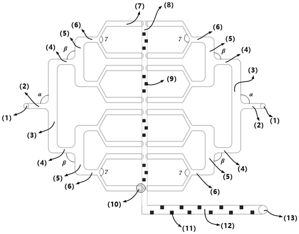
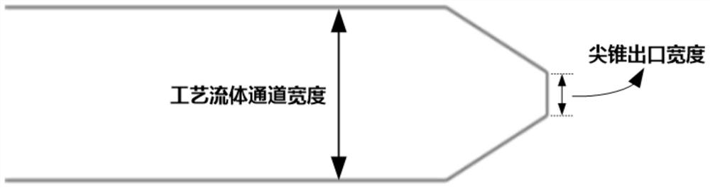
[0084] The microchannel mixer in the present embodiment comprises two stages of fluid distribution channels ( figure 1 ), the entrance channel is 500 μm wide, 500 μm deep, and 30 mm long. The width of the first-stage fluid distribution channel is 800 μm, the depth is 500 μm, and the length is 40 mm. The angle α between the inlet channel and the first-stage fluid distribution channel is 90°. The second-stage fluid distribution channel has a width of 500 μm, a depth of 300 μm, and a length of 15 mm. The angle β between the branch channel of the first-stage fluid distribution channel and the second-stage fluid distribution channel is 90°. The width of all process fluid channels is 250 μm, the depth is 250 μm, the length is 15 mm, and the width of the tapered outlet is 150 μm ( figure 2 ). The angle γ formed between the two process fluid channels and the branch channel of the second-stage fluid distribution channel connected together is 120°. The width of the fluid impingeme...

Embodiment 2

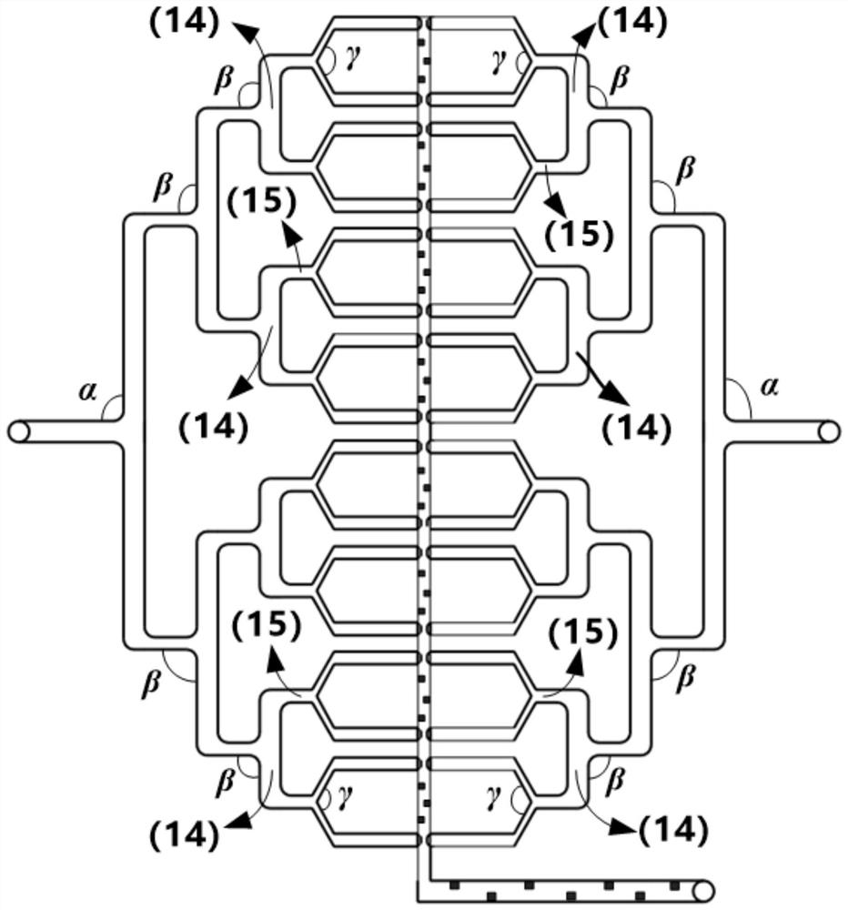
[0096] The microchannel mixer used in this embodiment comprises three stages of fluid distribution channels ( image 3 ), the third-stage fluid distribution channel has a width of 300 μm, a depth of 210 μm, and a length of 7 mm. The angle β between the branch channel of the second-stage fluid distribution channel and the third-stage fluid distribution channel is 90°. All other structural parameters of the microchannel mixer and the microscopic mixing measurement method are the same as in Example 1. The separation factor measured in this example is 0.0021, and the total pressure drop at the inlet and outlet is 117Pa.

Embodiment 3

[0098] The microchannel mixer used in this embodiment includes four stages of fluid distribution channels, the width of the fourth stage fluid distribution channel is 200 μm, the depth is 150 μm, and the length is 4 mm. The angle β between the branch channel of the third-stage fluid distribution channel and the fourth-stage fluid distribution channel is 90°. All other structural parameters of the microchannel mixer and the microscopic mixing measurement method are the same as in Example 2, the measured separation factor is 0.0018, and the total pressure drop at the inlet and outlet is 125Pa.

[0099] The comparison of Examples 1, 2 and 3 shows that increasing the number of stages of fluid distribution channels is conducive to enhancing the mixing effect.


PUM


Abstract

A multi-level structure micro-channel mixer, comprising a base plate and a sealing plate, the base plate is provided with two sample injection storage chambers, two inlet channels, two sets of liquid storage chambers arranged symmetrically on both sides of the fluid collision mixing chamber. A network of fluid distribution channels, two sets of process fluid channels, a fluid collision mixing chamber, a fluid enhancing mixing channel, and an outlet buffer chamber. The two fluids to be mixed are transported to the two sample injection storage chambers, respectively, and the two fluids enter the inlet channel through the sample injection storage chamber respectively, enter the process fluid channel after being distributed through the multi-stage fluid distribution channel, and flow out of the process fluid channel Two opposite colliding flows are formed. After mixing, a vortex or secondary flow is generated under the action of the fluid colliding with the baffles or internal components in the mixing chamber. The final mixed fluid mixture flows out of the mixer through the outlet buffer chamber. The multi-level structure microchannel mixer of the invention has the advantages of wide operating condition range, good mixing effect, high mass transfer coefficient, small pressure drop and low energy consumption.

Description

technical field [0001] The invention belongs to the technical field of chemical equipment, and in particular relates to a microchannel mixer, which is a device and method for rapid and efficient mixing of homogeneous and immiscible solution-liquid two-phase and gas-liquid two-phase fluids. Background technique [0002] A microchannel mixer refers to a micromixing device (W.Enrfeld, V.Hessel, H.Lowe, Microreactors: New Technology for Modern Chemistry, Wiley VCH, Weinheim, Germany, 2000; Chemical Micro Process Engineering, V. Hessel, H. Lowe, Wiley VCH, Weinheim, Germany, 2004). This equipment is a key component in the synthesis system of Micro Reaction Flow Chemistry (Micro Reaction Flow Chemistry) to realize the mixing of fluid materials, and its performance directly determines the conversion rate, selectivity, yield, energy consumption and product quality of the chemical reaction. Because the Reynolds number of the fluid flow in the micro-scale channel is small, it is in a...

Claims


Application Information

Patent Timeline
Patent Type & Authority Patents(China)
IPC IPC(8): B01F13/00B01F15/00
CPCB01F33/30B01F35/5312B01F25/23B01F25/431971B01F35/7182B01F2215/0422B01F2215/0427B01F2215/0431
Inventor 陈芬儿程荡刘敏杰黄华山姜梅芬王佳琦
Owner FUDAN UNIV
Why Eureka
Try Eureka