Heat-conducting profile floor

A floor and profile technology, applied in the floor field, can solve the problems of cumbersome construction, high pressure requirements of hot water pipes, high energy consumption of the system, etc., achieve high thermal conductivity and temperature uniformity, easy repair and maintenance, and simplify cumbersome processes Effect

Inactive Publication Date: 2021-01-12
王旭
View PDF6 Cites 0 Cited by
  • Summary
  • Abstract
  • Description
  • Claims
  • Application Information

AI Technical Summary

Problems solved by technology

[0002] At present, water heating or electric heating is mostly used in traditional floor heating systems on the market. In the water heating system, there are problems such as cumbersome construction, slow heating speed, low thermal conductivity, uneven heat distribution, and high pressure requirements for hot water pipes. Moreover, there are hidden dangers of blockage, freezing and cracking, and water leakage in hot water pipes; and in electric heating systems, there are problems such as high system energy consumption, high cost, and high line loss, and there are hidden dangers of short circuit and electric leakage; based on the above-mentioned traditional floor heating system The problem exists, and there is a baseboard-type heating device. The baseboard-type heating device has the advantages of high aesthetics, no space, heat dissipation around, and easy installation and maintenance. However, due to the main dependence on metal thermal conductivity and The heat radiation effect releases the heat generated by the internal heating device to the indoor environment. Most of the heat is still accumulated near the baseboard, which cannot quickly form convection with the indoor air and dissipate the heat to the indoor environment. The heat dissipation effect is poor and the temperature Therefore, if the way of heat conduction is improved at the floor end to overcome the shortcomings of baseboard heating equipment, it will further promote the application and promotion of heating systems

Method used


Image

  • Heat-conducting profile floor
  • Heat-conducting profile floor
  • Heat-conducting profile floor

Examples


Embodiment Construction

[0017] The following will clearly and completely describe the technical solutions in the embodiments of the present invention with reference to the accompanying drawings in the embodiments of the present invention. Obviously, the described embodiments are only some, not all, embodiments of the present invention. Based on the embodiments of the present invention, all other embodiments obtained by persons of ordinary skill in the art without making creative efforts belong to the protection scope of the present invention.

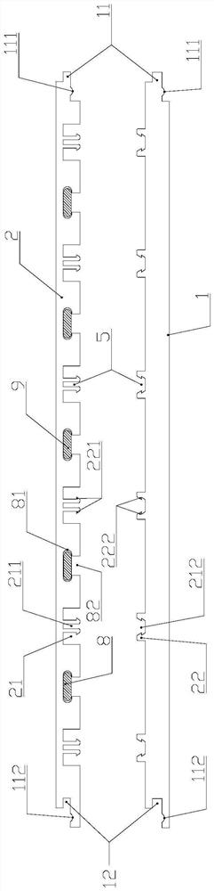
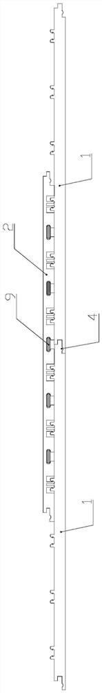
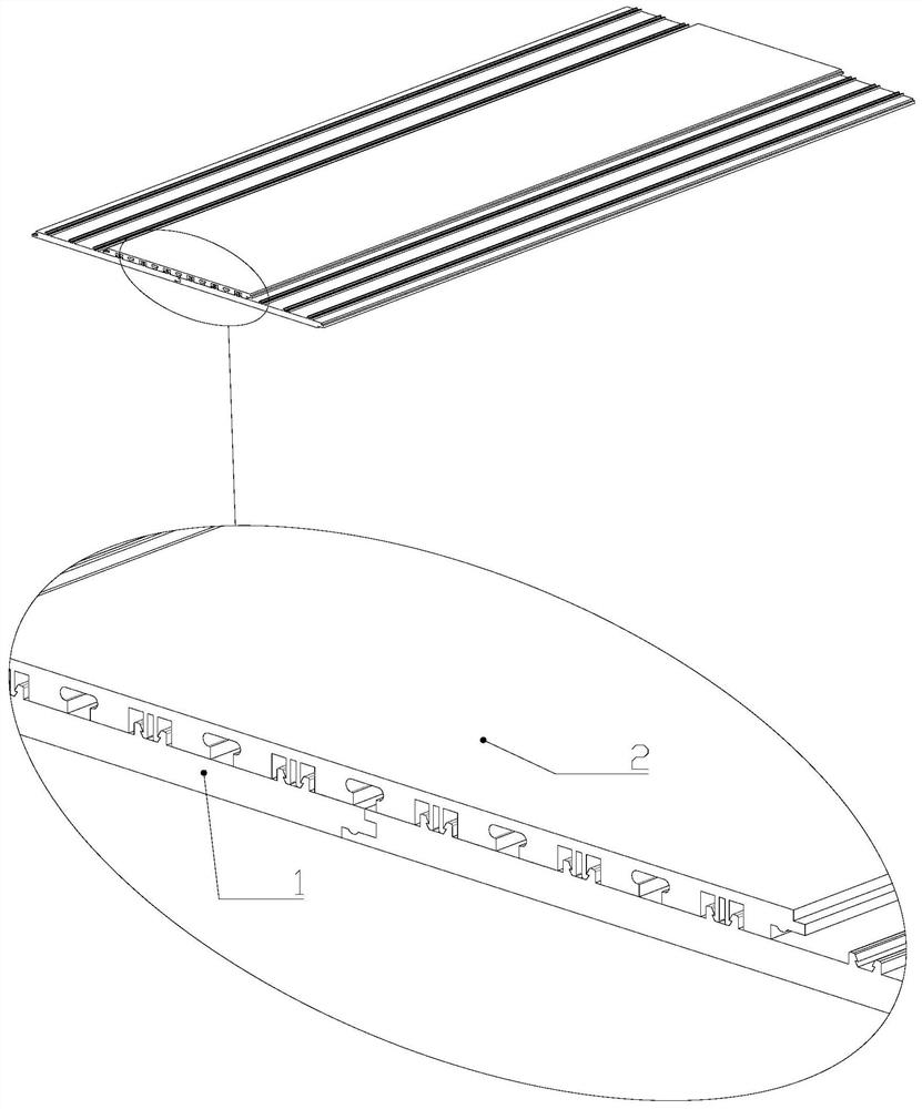
[0018] The invention provides a heat-conducting profile floor, such as figure 1 As shown, it includes a base plate 1 laid on the ground, a panel 2 that cooperates with the base plate 1 and covers the base plate 1, and the two ends of the base plate 1 or panel 2 are provided with joints 4 connected with the adjacent base plate 1 or panel 2, and the base plate 1 and the panel 2 are inserted through several pairs of mortise and tenon joints. Panel 2 is provided w...


PUM


Abstract

The invention relates to a heat-conducting profile floor. The floor comprises a bottom plate laid on the ground and a panel matching the bottom plate and covering the bottom plate, combination parts connected to the adjacent bottom plate or panel are arranged at the two ends of the bottom plate or panel, the bottom plate and the panel are connected in an inserted mode through a plurality of pairsof mortises and tenons, a plurality of parallel heat conduction pipe grooves are formed in the panel in a length direction, heat pipes are placed in the heat conduction pipe grooves, the evaporation ends of the heat pipes are heated by a skirting line plate heating device arranged on the wall surface, and the condensation ends of the heat pipes are in butt joint with the evaporation ends of the heat pipes of the adjacent panel. The heat pipes are adopted as passive heat transfer elements, the heat pipes have efficient heat conductivity and temperature uniformity, heat emitted by the skirting line plate heating device can be rapidly transferred to each place of a room, a temperature rise speed is high, the heat transfer efficiency is high, the defect that a traditional floor heating mode isvery slow in temperature rise is overcome, and energy consumption is greatly reduced.

Description

[0001] Technical Field: The present invention relates to a floor, in particular to a heat-conducting profile floor. Background technique [0002] At present, water heating or electric heating is mostly used in traditional floor heating systems on the market. In the water heating system, there are problems such as cumbersome construction, slow heating speed, low thermal conductivity, uneven heat distribution, and high pressure requirements for hot water pipes. Moreover, there are hidden dangers of blockage, freezing and cracking, and water leakage in hot water pipes; and in electric heating systems, there are problems such as high system energy consumption, high cost, and high line loss, and there are hidden dangers of short circuit and electric leakage; based on the above-mentioned traditional floor heating system The problem exists, and there is a baseboard-type heating device. The baseboard-type heating device has the advantages of high aesthetics, no space, heat dissipation ...

Claims


Application Information

Patent Timeline
Patent Type & Authority Applications(China)
IPC IPC(8): E04F15/024E04F15/02E04F15/06F28D15/02F28D15/04
CPCE04F15/02038E04F15/024E04F15/02405E04F15/06E04F2201/03E04F2201/043E04F2290/023F28D15/02F28D15/04
Inventor 王旭
Owner 王旭
Why Eureka
Try Eureka