Container type refrigeration station

A container-type, freezing station technology, applied in household refrigeration devices, cooling fluid circulation devices, water/sludge/sewage treatment, etc., can solve the problems of low integration, high cost and inflexibility, and achieve stable internal pressure, clear water effect

Pending Publication Date: 2021-01-12
艾尔科工程技术有限公司
View PDF0 Cites 3 Cited by
  • Summary
  • Abstract
  • Description
  • Claims
  • Application Information

AI Technical Summary

Problems solved by technology

[0004] In view of this, in order to solve the problems of large floor space, low integration, long on-site cross-construction period, high cost and inflexibility of the existing refrigeration station system, the present invention proposes a container-type refrigeration station, which includes a container body 1. Refrigeration unit 2, water pipes 3, automatic dosing device 4, Y-type filter 5, vertical pipeline pump 8, constant pressure water replenishment device 10, equipment main power supply 11, power cabinet 12 and closed cooling tower 14, closed The cooling water inlet pipe on the type cooling tower 14 enters the 32°C waterway to the refrigeration unit 2, and the cooling water outlet pipe 34 of the refrigeration unit 2 discharges the 37°C waterway to the closed cooling tower 14, forming a cooling water cycle, and the chilled water inlet pipe Enter the waterway discharged by the customer at 12°C, and the chilled water outlet pipe 32 discharges the waterway at 7°C to supply the customer, forming a chilled water cycle. When the PH value sensor 43 of the automatic dosing device 4 detects that the pH is abnormal, the automatic dosing device is started The dosing controller 42 on 4 adds medicine to the water pipe to ensure that the water quality is clear. When the pressure sensor 103 on the constant pressure water replenishment device 10 detects a pressure problem, the constant pressure water replenishment device 10 is activated to maintain the internal pressure of the water pipe 3 stable , when the client flow decreases or increases, the water flow balance is adjusted through the valve assembly 9

Method used


Image

  • Container type refrigeration station
  • Container type refrigeration station
  • Container type refrigeration station

Examples


Embodiment Construction

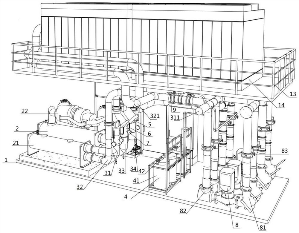
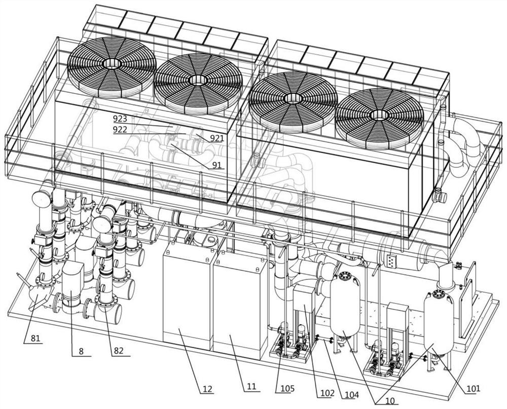
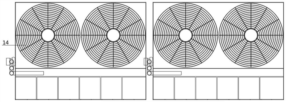
[0026] like figure 1 Shown is the structural representation of the container type freezing station of the present invention; figure 2 Shown is the structural representation of the container type freezing station of the present invention; image 3 Shown is the structural representation of closed cooling tower 14 of the present invention; Figure 4 Shown is the structural representation of the container type freezing station of the present invention; Figure 5 As shown, it is a schematic diagram of the waterway structure of the container type freezing station of the present invention; Image 6 Shown is a schematic structural view of the vertical pipeline pump 8 of the present invention.

[0027]A container-type refrigeration station, including a container body 1, a refrigeration unit 2, several water pipes 3, an automatic dosing device 4, a Y-shaped filter 5, a vertical pipeline pump 8, a constant pressure water supply device 10, and a main power supply 11 for the equipment ...


PUM


Abstract

A container type refrigeration station comprises a container body, a refrigerating unit, multiple water pipelines, an automatic dosing device, a Y-shaped filter, a vertical pipeline pump, a constant-pressure water supplementing device, an equipment main power supply, a power cabinet and a closed cooling tower, and is characterized in that the bottom of the closed cooling tower is fixedly connectedwith the top of the container body; the refrigerating unit comprises two compressors, a condenser and an evaporator, the multiple water pipelines are connected with the refrigerating unit; a Y-shapedfilter is arranged at the position, close to the refrigerating unit, of each water pipeline; and the constant-pressure water supplementing device, the equipment main power supply, the power cabinet,the automatic dosing device and the vertical pipeline pump are arranged in the container body; the automatic dosing device, the constant-pressure water supplementing device and the vertical pipeline pump are connected with the water pipelines; and the water pipelines include a chilled water supply pipe, a chilled water outlet pipe, a cooling water supply pipe and a cooling water outlet pipe.

Description

technical field [0001] The invention relates to the technical field of freezing stations, and more specifically, relates to a container-type freezing station. Background technique [0002] At present, air conditioners have been widely used in production and life. With the deepening of energy-saving and emission reduction strategies, there are more and more demands for the replacement of central air-conditioning system equipment in buildings. Since the central air-conditioning system cannot stop running, at the same time The size of the equipment is large, and it is difficult to replace the central air-conditioning system. The integrated, miniaturized, customized and mobile central refrigeration plant has become an urgent problem in the field of air conditioning. [0003] Existing refrigeration station systems are usually planned during the building or plant construction process. If the location of the refrigeration station is not planned during the initial planning process...

Claims


Application Information

Patent Timeline
IPC IPC(8): F25D17/02F25D29/00C02F9/04
CPCC02F1/001C02F1/66F25D17/02F25D29/005
Inventor 毛海军
Owner 艾尔科工程技术有限公司
Why Eureka
Try Eureka