Cassegrain telescope adjustment mechanism and adjustment method

An installation and adjustment method, Cassegrain's technology, applied in the direction of installation, optics, instruments, etc., can solve problems such as the complexity of the measurement process, and achieve the effects of reducing spherical aberration, convenient operation, and simple structure

Active Publication Date: 2021-01-15
SICHUAN UNIV +1
View PDF6 Cites 4 Cited by
  • Summary
  • Abstract
  • Description
  • Claims
  • Application Information

AI Technical Summary

Problems solved by technology

[0003] The Chinese patent application with the application number 201910881002.9 discloses a common-aperture optical system installation and adjustment method with a secondary mirror focusing mechanism. First, the deviation of the secondary mirror is measured by a center deviation measuring instrument, so that the axis of the guide rail is consistent with the rotation axis of the instrument turret. Then use the dual optical path measurement method to make the optical axis of the secondary mirror consistent with the axis of the guide rail. In the process, it is necessary to use a plane compensator to build the optical path, and use the interferometer to perform self-collimation adjustment, adjust the overall assembly position of the secondary mirror focusing mechanism, and make the wave image The difference at the zero position meets the requirements of the system wave aberration, which requires the use of structures such as interferometers, spherical lens compensators, and planar tooling reflectors. The entire measurement process is relatively complicated.

Method used


Image

  • Cassegrain telescope adjustment mechanism and adjustment method
  • Cassegrain telescope adjustment mechanism and adjustment method
  • Cassegrain telescope adjustment mechanism and adjustment method

Examples


Embodiment 1

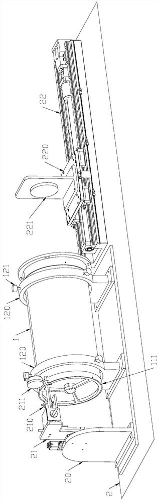
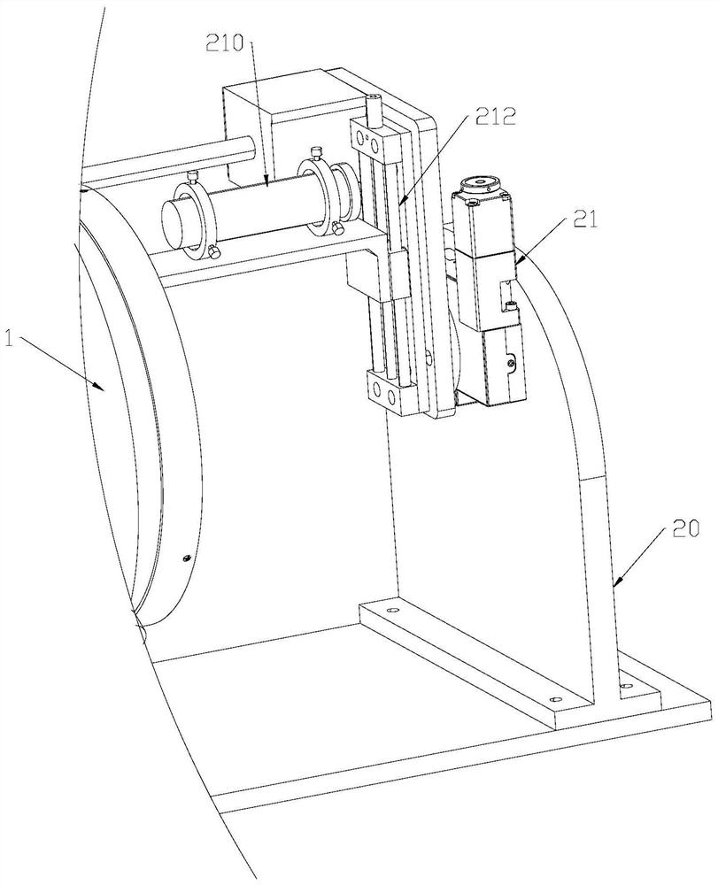
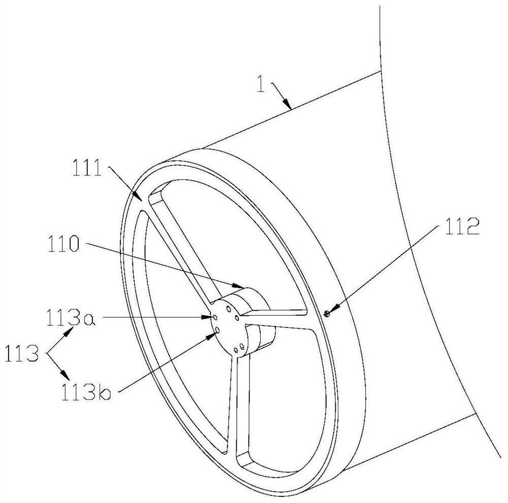
[0046] Such as Figure 1-4 As shown, the present embodiment provides a Cassegrain telescope assembly and adjustment mechanism, including a laser 210 for emitting light beams to the main mirror 10 of the Cassegrain telescope, and for driving the laser 210 to rotate around the optical axis of the main mirror 10 The rotary mechanism 21 and the light receiving member 221 vertically arranged on the optical axis of the main mirror 10, the optical axis of the outgoing light of the laser 210 is parallel to the optical axis of the main mirror 10; the light receiving member 221 is connected with the guide mechanism 22 so that The light receiving element 221 can move along the optical axis direction of the main mirror 10 .

[0047] Such as figure 1 and figure 2 As shown, in order to make the optical axis of the outgoing light of the laser 210 parallel to the optical axis of the primary mirror 10, a platform 2 is first provided, and the lens barrel 1 of the Cassegrain telescope is supp...

Embodiment 2

[0052] When assembling and adjusting the Cassegrain telescope, it is first necessary to make the optical axis of the outgoing light emitted by the laser 210 parallel to the optical axis of the primary mirror 10, that is, the first step of the assembling and adjusting method is as follows:

[0053] S1. Before installing the secondary mirror 11 , adjust the laser 210 so that the optical axis of the primary mirror 10 is parallel to the optical axis of the emitted light of the laser 210 .

[0054] In order to achieve the purpose in step S1, in this embodiment, the step S1 includes the following sub-steps:

[0055] S1.1. Set a light-receiving element at the focal point of the main mirror 10. The light-receiving element can be the light-receiving element 221 mentioned below, or it can be set separately. The light-receiving element 221 can be a CCD camera or a light screen. This implementation uses CCD camera, the outgoing light of the laser 210 is reflected by the main mirror 10 to ...


PUM


Abstract

The invention discloses a Cassegrain telescope adjustment mechanism and adjustment method, and the mechanism comprises a laser which is used for emitting a light beam to a primary mirror of a Cassegrain telescope, a rotating mechanism which is used for driving the laser to rotate around the optical axis of the primary mirror, and a light receiving part which is vertically disposed on the optical axis of the primary mirror. The optical axis of emergent light of the laser is parallel to the optical axis of the primary mirror, and the light receiving part can move in the direction of the opticalaxis of the primary mirror. When the Cassegrain telescope is adjusted, the optical axis of laser emitted by the laser emitter is parallel to the optical axis of the primary mirror, one end of the backsurface of the primary mirror is provided with a group of light receiving parts, a rotary laser and a movable light receiving part, and the change of the circle center and the diameter of a circle formed by a plurality of projection points on the light receiving parts at different positions is compared. The distance and the inclination angle between the primary mirror and the secondary mirror areadjusted, the influence of spherical aberration, coma, defocusing and other aberrations is reduced, and the measuring equipment is simple in structure, does not need to use an interferometer and is convenient to operate.

Description

technical field [0001] The invention relates to the field of optical imaging detection, in particular to a Cassegrain telescope assembly and adjustment mechanism and an assembly method. Background technique [0002] The Cassegrain telescope is a reflective telescope composed of two mirrors. It adopts the design of folded optics to greatly reduce the length of the lens barrel. The larger mirror is called the primary mirror, and the smaller one is called the secondary mirror. Mirror, the paraboloid of the primary mirror has a hole, and the telescope is imaged behind the primary mirror, and its focal point is called the Cassegrain focus; the parabolic primary mirror reflects and converges the parallel rays entering the telescope at the focal point, which is also the secondary mirror A focal point of the secondary mirror, and then the secondary mirror reflects the light for imaging; the above structure is described as a Cassegrain telescope in an ideal state. In the actual adjus...

Claims


Application Information

Patent Timeline
Patent Type & Authority Applications(China)
IPC IPC(8): G02B27/62G02B7/182
CPCG02B27/62G02B7/1822
Inventor 钱俊宏吴小龑张蓉竹刘国栋杨晓敏胡流森刘婷刘何伟
Owner SICHUAN UNIV
Why Eureka
Try Eureka