Stainless foil current collector for secondary battery positive electrodes

A secondary battery, stainless steel foil technology, applied in the field of current collectors

Active Publication Date: 2021-01-22
NIPPON STEEL CHEM &MATERIAL CO LTD
View PDF9 Cites 0 Cited by
  • Summary
  • Abstract
  • Description
  • Claims
  • Application Information

AI Technical Summary

Problems solved by technology

[0007] Furthermore, current collectors that do not contribute to the transmission and reception of Li ions are required to be as thin and lightweight as possible when they are installed in these electronic devices or automobiles.

Method used


Image

  • Stainless foil current collector for secondary battery positive electrodes
  • Stainless foil current collector for secondary battery positive electrodes
  • Stainless foil current collector for secondary battery positive electrodes

Examples


Embodiment 1

[0113] Ferritic stainless steel having the composition shown in Table 2 was smelted, subjected to normal hot rolling, pickling, cold rolling, and annealing, and then normal foil rolling (rolled material (hard material)) to produce a plate with a thickness of 10 μm stainless steel foil, prepare the specimen.

[0114] The surface hardness of the obtained stainless steel foil was calculated|required by Vickers hardness based on JIS Z 2244:2009. At this time, the test force (indentation load of the indenter) was set to 5 gf.

[0115] The corrosion resistance was evaluated by immersing a stainless steel foil test piece in an electrolyte close to the positive electrode environment and measuring the anode current. The electrolyte uses 1 mol / L (L refers to liter.) LiPF dissolved in a non-aqueous solvent (mixing ethylene carbonate and ethyl methyl carbonate at a volume ratio of 1:3) as an electrolyte 6 the resulting solution. Make a sample of stainless steel foil (thickness 10 μ m ×...

Embodiment 2

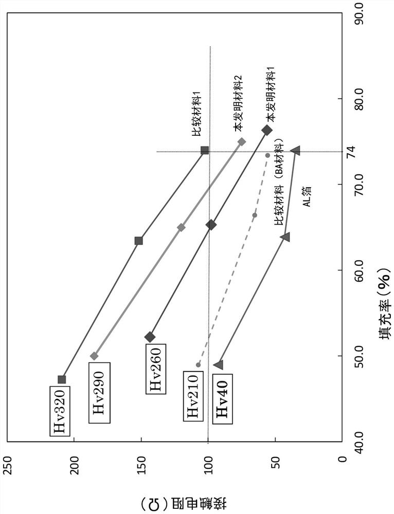
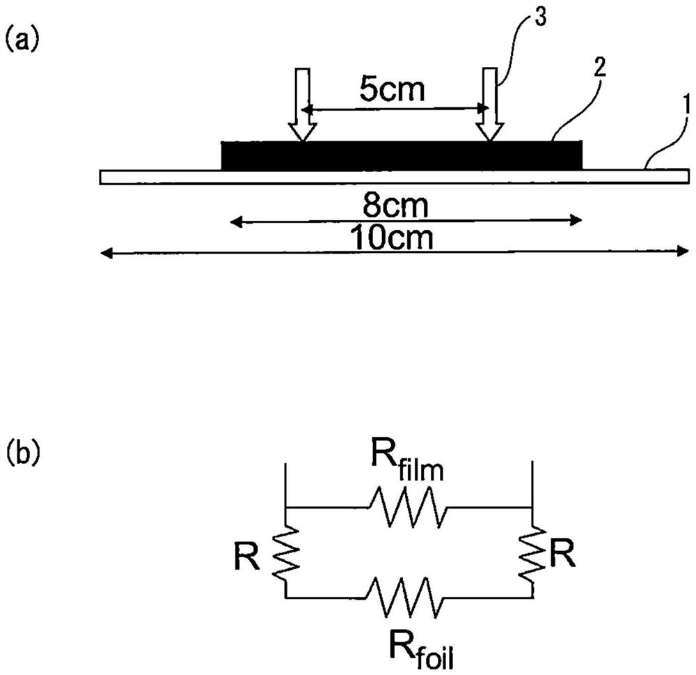
[0123] The filling rate of the positive electrode mixture and the electrical contact resistance with the stainless steel foil were measured in the positive electrode current collector obtained by coating the positive electrode mixture on the surface of the stainless steel foil and pressing it.

[0124] Stainless steel foil (rolled state material (hard material)) uses 1 steel in Table 2 ( figure 1 The inventive material 1) and 2 steel ( figure 1 The present invention material 2) and 7 steel ( figure 1 Comparative material 1). Stainless steel foils each having a plate thickness of 10 μm were used. For steel 7, steel subjected to BA treatment (annealing temperature 500°C) was used in order to change the surface hardness ( figure 1 The comparative material (BA material)) and steel without BA treatment (rolled state material (hard material)) ( figure 1 Comparative material 1). For comparison, Al foil (thickness: 20 μm) ( figure 1 Al foil). The surface hardness of each materi...


PUM

PropertyMeasurementUnit
thicknessaaaaaaaaaa
hardnessaaaaaaaaaa
hardnessaaaaaaaaaa

Abstract

The invention of the present application addresses the problem of increasing the mechanical strength of a current collector for secondary battery positive electrodes as well as the contact area between a positive electrode active material and a positive electrode mix to secure corrosion resistance against an alkali and an electrolyte solution while securing electrical conductivity when a stainlessfoil is applied to the current collector for the purpose of achieving the increase in the capacity of a lithium ion secondary battery and the reduction in the size or weight of a lithium ion secondary battery. Therefore, the purpose of the present invention is to provide a current collector for secondary battery positive electrodes using the stainless foil. The invention of the present application is a stainless foil current collector for secondary battery positive electrodes, which has a chemical composition having a reduced Cr content and containing a trace amount of Sn or a chemical composition containing Ti, and also has a thickness of 1 to 20 [mu]m inclusive and such surface hardness that the Vickers hardness is Hv 300 or less, so as to achieve corrosion resistance while decreasing the surface hardness.

Description

technical field [0001] The present invention relates to a current collector using a stainless steel foil used in a positive electrode of a secondary battery typified by a lithium ion battery. Background technique [0002] An electrode of a secondary battery typified by a lithium ion battery is composed of an electrode layer and a current collector. In the case of a lithium (Li) ion battery, the electrode layer is composed of an active material that can intercalate and deintercalate Li ions during charging and discharging, a conductive additive that helps improve electronic conductivity, and is used to connect the active materials to each other or the active material to the current collector. Body-bonded adhesive composition. The current collector plays a role of supporting the active material and passing current through a lead connected to the electrode layer and the outside. [0003] Conventionally, lithium cobalt oxide (LiCoO 2 , hereinafter referred to as "LCO". ), Li...

Claims


Application Information

Patent Timeline
Patent Type & Authority Applications(China)
IPC IPC(8): C22C38/00C22C38/28C22C38/54H01M4/13H01M4/131H01M4/136H01M4/505H01M4/525H01M4/58H01M4/66
CPCC22C38/28C22C38/54H01M4/131H01M4/505H01M4/525Y02E60/10C22C38/004C22C38/02C22C38/04C22C38/18C22C38/008C22C38/48C22C38/06C22C38/20C22C38/42C22C38/44C22C38/46C22C38/001C21D2211/005H01M4/661H01M2004/028H01M4/5825C22C38/002C22C38/50C22C38/52H01M4/136H01M4/669H01M4/134H01M4/662
Inventor 永田辰夫海野裕人福田将大藤本直树
Owner NIPPON STEEL CHEM &MATERIAL CO LTD
Why Eureka
Try Eureka