Optical medical device and using method thereof

A technology of medical devices and light sources, applied in phototherapy, radiation therapy, and heating appliances for therapeutic treatment, etc., can solve problems such as increasing patient treatment costs, unfavorable patient treatment, and damage to normal tissues, so as to avoid forced treatment and improve Therapeutic effect, the effect of precision therapy

Pending Publication Date: 2021-01-29
GUAN YEOLIGHT TECH CO LTD
View PDF5 Cites 2 Cited by
  • Summary
  • Abstract
  • Description
  • Claims
  • Application Information

AI Technical Summary

Problems solved by technology

[0003] In current photomedical devices, since the irradiated area and area of ​​the light source are fixed, the irradiated area is often larger than the treated area during treatment, so that normal skin tissue is also forced to receive treatment, which is unfavorable for the treatment of patients; In the prior art, there are some technical solutions that use image recognition to identify the treatment area, and the light source selectively treats the identified area to be treated. This method seems to be able to solve the above-mentioned problem of forced treatment, but in actual use During the process, the difference between the treatment area and the normal skin tissue is often not obvious in image development, and it needs to be observed carefully with the naked eye. At this time, the recognition accuracy of the image recognition method is very poor, and sometimes even misidentification occurs. It cannot fundamentally solve the above-mentioned problems of forced treatment
[0004] At present, the light source used for optical medical devices is strong light source and weak light source, and the strong light source is mainly 10000mW / cm 2 The laser light source, while the weak light source is mainly 100mW / cm 2 The light source within the range can be OLED or LED. Optical medical devices with strong light sources are not easy to wear, and most optical medical devices can only be used in hospitals, and patients need to keep still for a long time during the illumination time. Bring a lot of inconvenience, increased the treatment expense of the patient simultaneously
And for diseases in reproductive organs and private parts, patients are generally taboo. In addition, strong light sources will damage normal tissues due to too strong power when treating diseases. In addition, the uniformity of laser light source and LED light emission is relatively high. Poor, not conducive to the treatment of larger lesions

Method used


Image

  • Optical medical device and using method thereof
  • Optical medical device and using method thereof
  • Optical medical device and using method thereof

Examples


Embodiment 1

[0076] This embodiment provides a photomedical device, including:

[0077] The OLED light source 10 is used to provide a therapeutic light source, including several independently luminous light emitting areas;

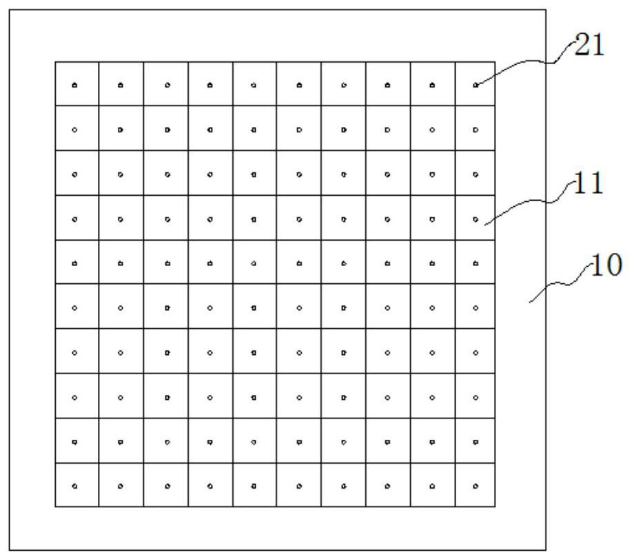
[0078] The sensing module 20 is used for sensing the skin or tissue status in the treatment area, including several sensors 21 distributed on the working surface of the photomedical device;

[0079] The control module 30 is configured to receive the state signal sensed by the sensor, perform calculation and analysis on the state signal to determine the area to be treated, light up the light-emitting area corresponding to the area to be treated, and control the lighting of different areas according to the state signal. Luminous brightness or wavelength.

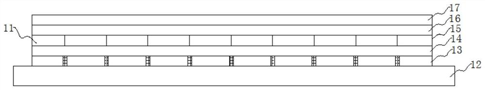
[0080] Wherein, the OLED light source 10 is a flexible OLED screen body, which is uniformly provided with an independent light-emitting area 11, and the shape of the light-emitting area 11 can be arbitrary, for exampl...

Embodiment 2

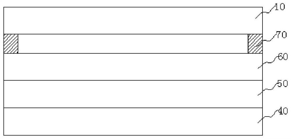
[0136] This embodiment is on the basis of embodiment 1, as Figure 13 and Figure 14 As shown, any side of the OLED light source is provided with a cooling layer 80 . The cooling layer 80 is composed of a hydrogel layer 81 or is composed of a hydrogel layer 81 and a temperature regulation layer 82; the temperature regulation layer 82 is composed of a semiconductor patch or a micro-resistance; the control module 30 is configured for The temperature of the temperature regulation layer 82 is controlled by controlling the operating current of the semiconductor patch or the micro-resistor.

[0137] At this time, the cooling layer 80 can be activated during the blue light analgesic stage, and perform cooling and analgesic effects after the red light treatment. The adjustable temperature range of the temperature-regulating layer is 5-35°C, preferably 15-25°C; the temperature-regulating layer 82 can also be activated during the red light therapy stage to cool down when the temperatu...

Embodiment 3

[0158] Such as Figure 18 As shown, the photomedical device provided in this embodiment is based on Embodiment 2, the OLED light source 10, the sensing module 20 and the control module 30 form a flexible sheet structure 120; the flexible sheet structure is curled and attached to the support On the body, such as the outer surface of the cylindrical support body 110 .

[0159] At this time, the diameter of the entire photomedical device ranges from 1 mm to 50 mm; the material of the cylindrical support body can be, for example, rubber, resin or TPU. At this time, the device can be used for in vivo treatment. After wrapping the OLED light source 10 on the cylindrical support 110, perform glue sealing treatment. The glue can be PU glue of AB component, mix the AB component according to the ratio of 1:1, and package it by pulling method. Curing at room temperature for 12 hours can achieve the purpose of waterproofing. In order to ensure the biological safety performance during use...


PUM

PropertyMeasurementUnit
Thicknessaaaaaaaaaa

Abstract

The invention discloses an optical medical device and a using method thereof. The device comprises an OLED light source, an induction module and a control module. The OLED light source is used for providing a treatment light source and comprises a plurality of light-emitting areas which emit light independently; the sensing module is used for sensing the skin or tissue state of the treatment areaand comprises a plurality of sensors distributed on the working surface of the optical medical equipment; the control module is configured to receive the state signal sensed by the sensor, determine ato-be-treated area according to the state signal, and lighten a light-emitting area corresponding to the to-be-treated area with brightness corresponding to the state signal. The sensing module is arranged on the surface of the optical medical device, and the sensor of the sensing module is in direct contact with the skin to sense the state signal of the skin, so that the treatment area can be accurately judged, the light-emitting area corresponding to the treatment area is opened, accurate treatment is realized, forced treatment of normal skin tissues is avoided, normal skin tissues are protected, and the treatment effect is improved.

Description

technical field [0001] The invention relates to the technical field of medical devices, in particular to an optical medical device and a method for using the same. Background technique [0002] In recent years, phototherapy has achieved remarkable results in the clinical treatment of diseases, and has become one of the main methods for treating diseases. Photodynamic therapy is a method of directly using light or using light and drugs to treat diseases. It has been applied to clinical medicine. There are two main methods of photodynamic therapy, one is direct phototherapy, and the other is medical treatment in which light and drugs (also known as photosensitizers) act synergistically. Among them, direct phototherapy is to directly irradiate the affected area with one kind of light or multiple kinds of light to sterilize, disinfect, promote cell metabolism, promote cell regeneration, promote cell secretion of some chemical substances (such as serotonin, etc.) and promote blo...

Claims


Application Information

Patent Timeline
IPC IPC(8): A61N5/06A61F7/02
CPCA61F7/02A61F2007/0219A61N5/062A61N2005/0626A61N2005/0653A61N2005/0663
Inventor 于倩倩谢静许显斌胡永岚李栋栋
Owner GUAN YEOLIGHT TECH CO LTD
Why Eureka
Try Eureka