Nitrogen blowing instrument automatic control device and monitoring control method

An automatic control device and nitrogen blowing instrument technology, applied in the detection field, can solve the problems of measurement accuracy, temperature sensitivity, large volume, etc., and achieve the effects of avoiding errors and labor, ensuring accuracy and speed, and ensuring concentration efficiency

Active Publication Date: 2021-01-29
中标华谱(山东)智能科技有限公司
View PDF17 Cites 1 Cited by
  • Summary
  • Abstract
  • Description
  • Claims
  • Application Information

AI Technical Summary

Problems solved by technology

However, the ultrasonic liquid level gauge used in the literature is sensitive to temperature. At the same time, when there is water mist, it will affect the accuracy of the measurement, and the measurement has a certain blind area, and the volume is large. When the diameter of the test tube is small, it is not convenient to arrange. Compared with the traditional Nitrogen blowing device, the equipment is too complicated and expensive; in addition, due to the uncertain concentration of different sample solutions, the method of determining the end time of concentration according to the height of the sample solution is not applicable
[0004] Most of the existing technologies only consider the control of the nitrogen blowpipe and the height of the liquid level during the concentration process. In addition, only the rise and fall of the test tube or the nitrogen blowpipe is controlled separately, and the test tube cannot be controlled to enter and exit the water bath. Manual operation is still required; The low concentration of the sample solution leads to complicated liquid surface churning. The liquid level measurement device used in the prior art cannot accurately collect and judge the actual height of the liquid level, resulting in low accuracy of the control process and the inability to achieve optimal concentration efficiency; in addition, The lifting device in the prior art is too complicated to be suitable for test tubes with different diameters, especially small diameter test tubes, resulting in increased nitrogen consumption and reduced concentration efficiency, and cannot realize the simultaneous control of more than one group of different concentrated samples

Method used


Image

  • Nitrogen blowing instrument automatic control device and monitoring control method
  • Nitrogen blowing instrument automatic control device and monitoring control method
  • Nitrogen blowing instrument automatic control device and monitoring control method

Examples


Embodiment 1

[0067] An automatic control device for a nitrogen blowing instrument, including an information collection system, a fixed mobile mechanism, and a control system;

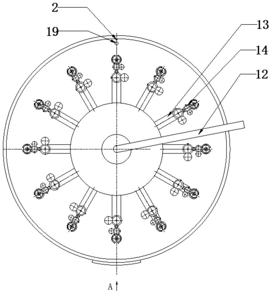
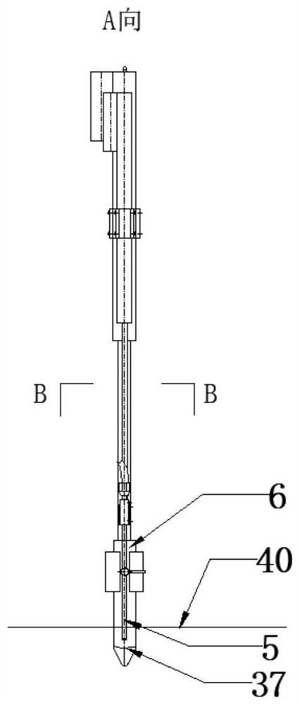
[0068] The information collection system includes a macro camera 1 installed on a fixed mobile mechanism and a liquid level sensor 2 in a water bath environment; the macro camera 1 is used to collect the liquid level of the sample in the transparent test tube 6;

[0069] The fixed moving mechanism includes a first lifting mechanism 3 and a second lifting mechanism 4;

[0070] The first lifting mechanism 3 is used to drive the nitrogen blowing pipe 5 to move up and down, and extend the nitrogen blowing pipe 5 into the transparent test tube 6 to blow nitrogen to the sample in the transparent test tube 6;

[0071] The second lifting mechanism 4 is used to drive the transparent test tube 6 to move up and down, so that the transparent test tube 6 is automatically immersed in or out of the water bath environment;

[0072...

Embodiment 2

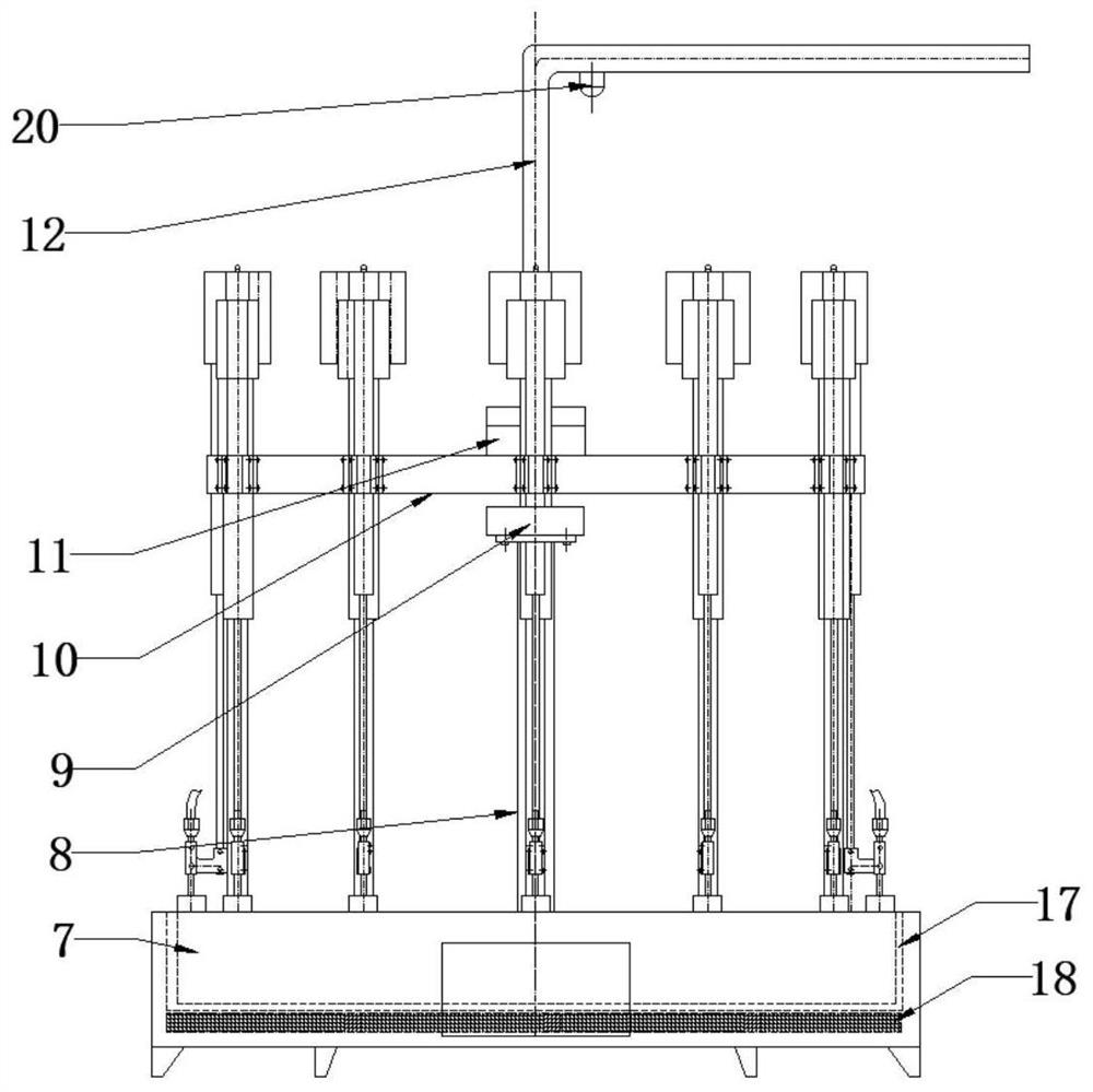
[0074] On the basis of Embodiment 1, a supporting mechanism is added, and the supporting mechanism includes a base 7, a vertical column 8, a vertical servo motor 9, a horizontal circular tray 10, a gas-electric slip ring 11 and a gas-electric sheath tube 12, and the vertical column 8 Be arranged at the center of described base 7, be provided with a vertical servomotor 9 at the top of vertical column 8, described horizontal round tray 10 is fixed on the top of vertical servomotor 9 motor shafts, is installed in the center of described horizontal round tray 10 top surfaces. There is a gas-electric slip ring 11, and the gas-electric slip ring 11 is connected to the gas-electric sheath pipe 12 on the top of the gas-electric slip ring. The electric control circuit is arranged inside the gas-electric sheath pipe 12. The horizontal circular tray 10 Horizontal rods 13 are arranged on the circumference of each horizontal rod 13, and double snap rings 14 are installed on the outer ends o...

Embodiment 3

[0076]A gas supply system is added to the technology of embodiment two, and the gas supply system includes a nitrogen main pipeline and a nitrogen branch 15; a miniature electromagnetic shut-off valve and an electronically controlled pressure regulating valve are installed on the nitrogen branch 15, and the miniature The electromagnetic cut-off valve and the electric control pressure regulating valve are connected with the main nitrogen pipeline through pipelines, and the main electric control shut-off valve and the total electric control pressure regulating valve are installed on the nitrogen main pipeline, and the main nitrogen pipeline passes through the gas-electric slip ring 11 is connected with each nitrogen branch 15; preferably, the nitrogen branch 15 is connected with the nitrogen blow pipe 5 through a tightening nut 16; The electric control wires of the total pressure regulating valve are all connected with the control system, and are used to control the nitrogen blow...


PUM


Abstract

The invention relates to the technical field of detection, and particularly relates to a nitrogen blowing instrument automatic control device which mainly comprises an information acquisition system,a fixed moving mechanism and a control system. Technical improvement is carried out on the basis of existing nitrogen blowing instrument equipment, ascending and descending of a nitrogen blowing pipeand a transparent test tube can be controlled respectively, a nitrogen blowing condition of a sample in the test tube is monitored and adjusted in real time, the nitrogen blowing pipe is automaticallyclosed and ascended after the requirement is met, and the transparent test tube also ascends to the position above a liquid level of a water bath environment; and an audio-video prompt is sent. The device replaces manual operation, realizes automation, improves the detection quality and efficiency, and overcomes defects of inaccurate liquid level height judgment and inaccurate judgment on a concentration end node in the concentration process in the prior art.

Description

technical field [0001] The invention relates to the technical field of detection, in particular to an automatic control device and a monitoring control method for a nitrogen blowing instrument. Background technique [0002] The nitrogen blowing instrument is often used to concentrate the sample during the inspection process. Before the nitrogen blowing, the operator must observe and manually adjust the distance between the nitrogen blowing pipe and the sample and the depth of the test tube immersed in the constant temperature water bath. During the nitrogen blowing process Because the sample concentration in each test tube takes different time, it is necessary to observe the distance between the sample liquid surface and the nitrogen blowpipe at all times. If it is too large, you need to manually adjust the distance from the nitrogen blowpipe to the sample liquid surface. The time it takes for the sample to meet the concentration requirements is inconsistent, so it is necess...

Claims


Application Information

Patent Timeline
IPC IPC(8): G01N1/40G01F23/292
CPCG01N1/4022G01F23/2921Y02E30/30
Inventor 王望舒吴建国张云霄李俏李乐义李义民
Owner 中标华谱(山东)智能科技有限公司
Why Eureka
Try Eureka