Self-heating metal hydride hydrogen storage system and hydrogen charging and discharging method

A hydride, self-heating technology, applied in the field of hydrogen storage system, can solve the problems of high safety factor, insufficient volume energy density, high power consumption of hydrogen compression, etc., achieve high safety factor and solve the effect of low temperature start-up difficulties

Active Publication Date: 2021-02-02
SHANDONG UNIV OF SCI & TECH
View PDF10 Cites 13 Cited by
  • Summary
  • Abstract
  • Description
  • Claims
  • Application Information

AI Technical Summary

Problems solved by technology

The main bottleneck of existing mobile hydrogen storage technology is insufficient volumetric energy density or insufficient mass energy density
High-pressure gaseous hydrogen storage is currently the most commercialized hydrogen storage technology, but the safety and failure mechanism of hydrogen storage tanks need to be further studied. The power consumption of hydrogen compression in the hydrogenation process is large, and the carbon fiber wrapped around the storage tank is still a technical bottleneck in my country.
[0003] Metal hydride hydrogen storage materials have the advantages of high safety factor, high volumetric energy density, and high purity of hydrogen. However, their hydrogen absorption and desorption temperatures are relatively high. If they are used to supply hydrogen for hydrogen fuel cells, additional heating devices are required, resulting in structural Complex and difficult to manage, thus limiting its large-scale production application
Although scholars at home and abroad have studied various methods to reduce the hydrogen absorption and desorption temperature, they have not yet found a method that has high hydrogen storage density, fast hydrogen absorption and desorption rate, stable structure and low price under mild conditions (hydrogen absorption and desorption temperature is less than 100°C). Efficient hydrogen storage materials suitable for mass production

Method used


Image

  • Self-heating metal hydride hydrogen storage system and hydrogen charging and discharging method

Examples


Embodiment Construction

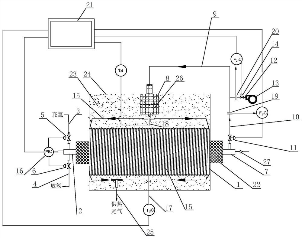
[0034] With reference to the accompanying drawings, a self-heating metal hydride hydrogen storage system includes a hydrogen storage system and a hydrogen catalytic combustion heating system for heating the hydrogen storage system. The hydrogen storage system includes a hydrogen storage tank 1, in which a metal hydride hydrogen storage material is installed, the hydrogen storage tank 1 is arranged horizontally, and a hydrogen charging and discharging port 2 is provided at one end of the hydrogen storage tank 1 , the hydrogen charging and discharging port 2 is connected to the hydrogen charging pipeline 3 and the hydrogen discharging pipeline 4. A first control valve 5 is set on the hydrogen charging pipeline 3 , and a second control valve 6 is set on the hydrogen discharge pipeline 4 . The other end of the hydrogen storage tank 1 is provided with a hydrogen outlet port 7 for supplying hydrogen to the hydrogen catalytic combustion heating system.

[0035] The hydrogen catalyti...


PUM


Abstract

The invention discloses a self-heating metal hydride hydrogen storage system which comprises a hydrogen storage system and a hydrogen catalytic combustion heating system used for heating the hydrogenstorage system. The hydrogen storage system comprises a hydrogen storage tank, a metal hydride hydrogen storage material is contained in the hydrogen storage tank, a hydrogen charging and dischargingport is formed in one end of the hydrogen storage tank, and a hydrogen outlet port used for supplying hydrogen to the hydrogen catalytic combustion heating system is formed in the other end of the hydrogen storage tank. The hydrogen catalytic combustion heating system comprises a hydrogen catalytic combustor, a catalyst is contained in the hydrogen catalytic combustor, the gas inlet end of the hydrogen catalytic combustor is connected with a mixed gas conveying main pipeline, the gas outlet end of the hydrogen catalytic combustor is connected with a heat conduction pipe, and the heat conduction pipe is wound on the hydrogen storage tank. According to the self-heating metal hydride hydrogen storage system, part of hydrogen in the hydrogen storage tank is separated out to be subjected to catalytic combustion on the catalyst in the combustor, and the hydrogen storage tank is heated through high-temperature gas generated after combustion, so that autonomous temperature control and autonomous heat supply can be achieved, and a heating system does not need to be additionally arranged.

Description

technical field [0001] The invention relates to the field of hydrogen storage systems, in particular to a self-heating metal hydride hydrogen storage system and a method for charging and discharging hydrogen using the hydrogen storage system. Background technique [0002] Hydrogen fuel cells have many advantages, but their commercialization process, especially in mobile applications such as new energy vehicles and drones, is restricted by the current development level of mobile hydrogen supply technology. Under standard conditions, the density of hydrogen is only 0.0899g / L, and the volumetric energy density is very low. At the same time, the boiling point of hydrogen is -253°C, making it difficult to liquefy. The main bottleneck of the existing mobile hydrogen storage technology is insufficient volume energy density or insufficient mass energy density. High-pressure gaseous hydrogen storage is currently the most commercialized hydrogen storage technology, but the safety an...

Claims


Application Information

Patent Timeline
Patent Type & Authority Applications(China)
IPC IPC(8): F17C11/00F17C1/12F17C13/00F17C13/02F17C13/04
CPCF17C11/005F17C13/04F17C1/12F17C13/02F17C13/002F17C2201/0104F17C2203/035F17C2223/0138F17C2225/0123F17C2250/032Y02E60/32
Inventor 张同环于昊涂宝峰周仕学韩宗盈
Owner SHANDONG UNIV OF SCI & TECH
Why Eureka
Try Eureka