All-fiber mode conversion device and method and detection device

A mode conversion and mode converter technology, applied in optical mode multiplexing systems, optical fiber transmission, measurement devices, etc., can solve problems such as low conversion efficiency, and achieve the effects of low cost, high mode conversion efficiency, and simple manufacturing process

Pending Publication Date: 2021-02-02
SHANGHAI UNIV
View PDF5 Cites 7 Cited by
  • Summary
  • Abstract
  • Description
  • Claims
  • Application Information

AI Technical Summary

Problems solved by technology

[0004] The purpose of the present invention is to provide an all-optical fiber mode conversion device and method and detection device, which can generate high-order OAM modes and realize high-efficiency mode conversion of not less than 99%, so as to solve the problems existing in optical fiber mode conversion devices in the prior art. The problem of inefficiency

Method used


Image

  • All-fiber mode conversion device and method and detection device
  • All-fiber mode conversion device and method and detection device
  • All-fiber mode conversion device and method and detection device

Examples


Embodiment 1

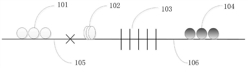
[0044] figure 1 It is a structural diagram of an all-fiber mode conversion device of the present invention. Such as figure 1 As shown, the all-fiber mode conversion device includes a first polarization controller 101, a mode filter 102, a mode converter 103, a second polarization controller 104, an optical fiber 105 and an optical fiber 106; the output end of the first polarization controller 101 The input end of the mode converter 103 is connected through an optical fiber 105, and the output end of the mode converter 103 is connected with the input end of the second polarization controller 104 through an optical fiber 106. The first polarization controller 101 is used to adjust the beam to circularly polarized light or linear polarization. For polarized light, the mode converter 103 uses carbon dioxide laser to write LPFG on the few-mode fiber 106 to achieve mode conversion, and the second polarization controller 104 is used to adjust the phase difference between the vector ...

Embodiment 2

[0046] This embodiment is basically the same as Embodiment 1, and the special features are as follows:

[0047] The light generated by the light source first passes through the polarization controller 101. The polarization controller 101 is a single-mode fiber polarization controller corresponding to the single-mode fiber 105. The polarization controller 101 adjusts the light to circularly polarized light or linearly polarized light with a specific polarization direction. Afterwards, the light beam passes through a section of few-mode fiber 106 and passes through a mode converter 103 to transform the LP 01 The mode is converted to a higher-order LP core mode. It should be emphasized that the circularly polarized light entering the mode converter 103 converts to the vector mode of the LP higher-order core mode, and the linearly polarized light entering the mode converter 103 converts to obtain the linear polarization mode of the LP higher-order core mode. The converted high-or...

Embodiment 3

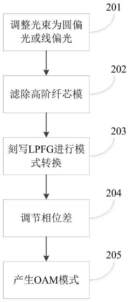
[0051] This all-optical fiber mode conversion method adopts the above-mentioned conversion device to operate, and is characterized in that the operation steps are as follows:

[0052] 1) The light beam generated by the light source passes through the first polarization controller of the all-fiber mode conversion device, and the light beam is adjusted to circularly polarized light or linearly polarized light; the all-fiber mode conversion device includes: a first polarization controller, a mode converter, The second polarization controller; the output end of the first polarization controller is connected to the input end of the mode converter through an optical fiber, and the output end of the mode converter is connected to the input end of the second polarization controller through an optical fiber , the mode converter realizes mode conversion by a long-period fiber grating written on a few-mode fiber by a carbon dioxide laser;

[0053] 2) the light beam passing through the fi...


PUM

PropertyMeasurementUnit
contrastaaaaaaaaaa
conversion efficiencyaaaaaaaaaa

Abstract

The invention discloses an all-fiber mode conversion device and method and a detection device. The conversion device comprises a first polarization controller, a mode converter and a second polarization controller, wherein the output end of the first polarization controller is connected with the input end of the mode converter through an optical fiber, the output end of the mode converter is connected with the input end of the second polarization controller through an optical fiber, and the first polarization controller is used for adjusting a light beam to be circularly polarized light or linearly polarized light. The mode converter realizes mode conversion by using a long-period fiber bragg grating inscribed on a few-mode fiber by carbon dioxide laser, and the second polarization controller is used for adjusting the phase difference between vector HE odd-even modes or EH odd-even modes so as to generate an orbital angular momentum mode. By adopting the device and the method providedby the invention, mode conversion with wide bandwidth, high purity mode and high conversion efficiency can be realized, and the device and the method have wide application value in a mode division multiplexing optical fiber communication system.

Description

technical field [0001] The invention relates to the field of optical fiber communication, in particular to an all-fiber mode conversion device, method and detection device. Background technique [0002] In the mode-division multiplexing communication system, devices that need to realize mode conversion, the existing mode conversion devices generally include: free-space optical element mode converter, because this type of mode converter is a free-space device, it is relatively complicated and has a large insertion loss ; The planar optical waveguide mode converter has the problem of mode output coupling loss in the all-fiber communication system, and the price is more expensive; the all-fiber mode converter is more suitable for use in the optical fiber communication system than the previous two mode converters. [0003] Current all-fiber-based mode-selective couplers can combine LP 01 The mode is converted to a high-order LP mode, and a first-order OAM (Orbital Angular Momen...

Claims


Application Information

Patent Timeline
Patent Type & Authority Applications(China)
IPC IPC(8): G02B6/27G02B6/26H04B10/25H04J14/04G01M11/00
CPCG02B6/2766G02B6/264H04J14/04G01M11/30
Inventor 刘云启赵云鹤刘祖耀赵馨艺牟成博
Owner SHANGHAI UNIV
Why Eureka
Try Eureka