
High-strength electromagnetic pulse protection structure material

An electromagnetic protection and electromagnetic pulse technology, which is applied in the direction of electrical components, lamination, antennas, etc., can solve the problems that the electrical performance index is difficult to meet the actual application requirements, the electrical performance is quite different from the design value, and the mechanical and electrical properties are poor. Achieve the effect of improving the mechanical properties of the material structure, improving the mechanical properties, and increasing the molding speed

Pending Publication Date: 2021-02-05
CHINA SHIP DEV & DESIGN CENT
View PDF2 Cites 2 Cited by
  • Summary
  • Abstract
  • Description
  • Claims
  • Application Information

AI Technical Summary

Problems solved by technology

However, the existing electromagnetic pulse protection structural materials generally have poor mechanical properties (flat compressive strength, bending strength, etc.) and electrical properties. Poor, material collapse and deformation under high temperature and high pressure cause a large difference between the electrical properties and the design value, in addition to the poor structural mechanics of materials such as foam, honeycomb, rubber, etc., resulting in the overall structural mechanics and electrical performance indicators of the material after molding are difficult to meet practical applications Require

Method used


Image

  • High-strength electromagnetic pulse protection structure material
  • High-strength electromagnetic pulse protection structure material

Examples


Embodiment 1

[0033] A high-strength electromagnetic pulse protection structure material, the preparation steps are as follows:

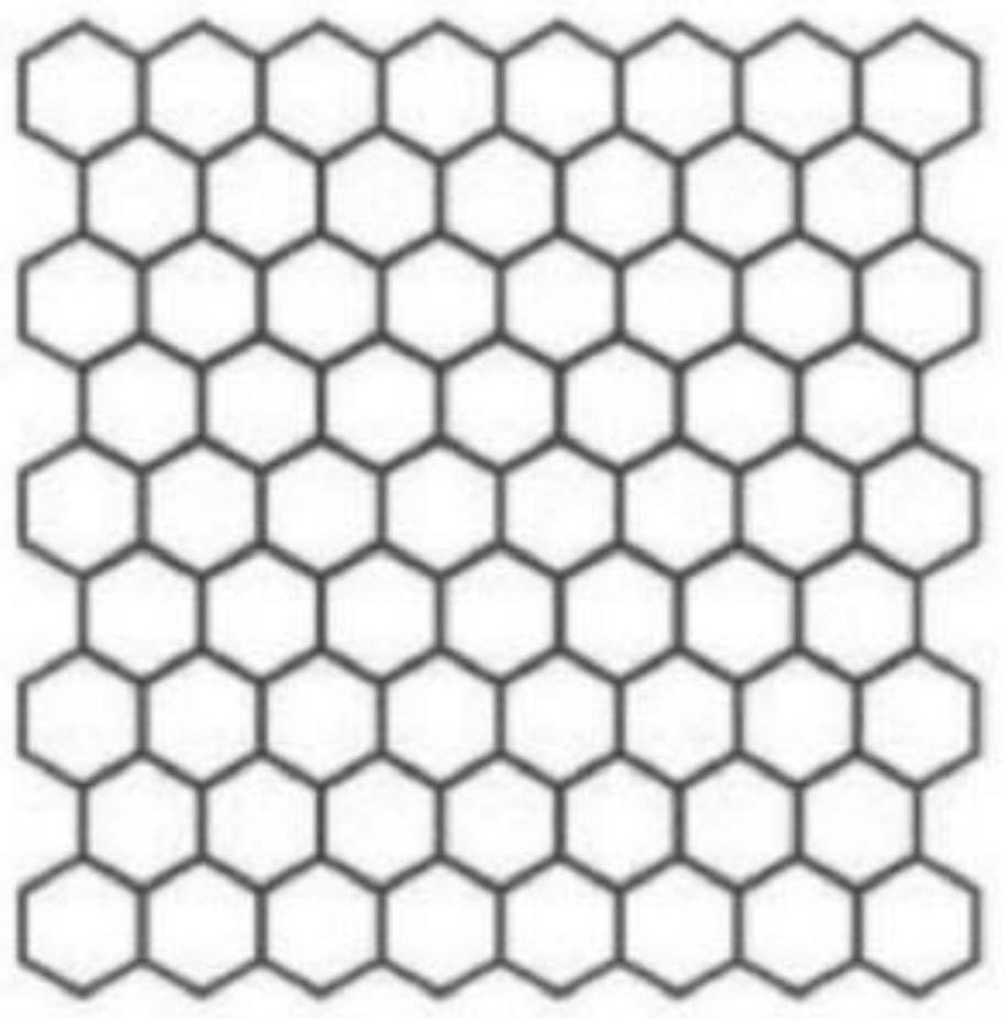
[0034] 1) In 4 pieces of polycarbonate lattice structure materials (obtained by the structure units with a side length of 2.5mm, a thickness of 5mm, and tip protrusions in a honeycomb lattice distribution, the planar structure schematic diagram is as follows figure 2 As shown, the size is 300mm×300mm×21mm) the surface is impregnated with acetylene carbon black coating material (obtained by mixing acetylene carbon black with an average particle size of 10 μm into epoxy resin, room temperature curing agent is added to epoxy resin, and acetylene carbon black coating The mass percentage of acetylene carbon black in the material is 20%) and cured at room temperature to obtain 4 lattice structure electromagnetic protection layers, and the quality of the acetylene carbon black coating in the 4 lattice structure electromagnetic protection layers is made 100% by adjusting...


PUM

PropertyMeasurementUnit
thicknessaaaaaaaaaa
thicknessaaaaaaaaaa
particle diameteraaaaaaaaaa

Abstract

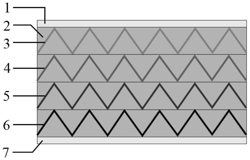
The invention relates to a high-strength electromagnetic pulse protection structure material which is composed of an electromagnetic protection layer and skin layers covering the upper surface and thelower surface of the electromagnetic protection layer. The electromagnetic protection layer is obtained by superimposing multiple layers of lattice structure electromagnetic protection layers; each lattice structure electromagnetic protection layer is composed of a lattice structure material obtained by honeycomb lattice distribution of structure units with tip protrusions and an electromagneticabsorption loss coating layer coating the lattice structure material, and the mass percentages of the electromagnetic absorption loss coating layer in the lattice structure electromagnetic protectionlayers are gradually increased from top to bottom and are distributed in a gradient mode. An internal gap of the interior of the electromagnetic protection layer is filled with a light high-wave-transmission resin-based reinforcing material. According to the high-strength electromagnetic pulse protection structure material provided by the invention, the thickness / total thickness of each electromagnetic protection layer is easier to accurately control under the room temperature curing condition, the controllability of the electromagnetic absorption performance is stronger, and meanwhile, the structural mechanical property of the material is improved by pouring the light high-wave-transmission resin-based reinforcing material.

Description

technical field [0001] The invention belongs to the technical field of devices for absorbing antenna radiation waves, and in particular relates to a high-strength electromagnetic pulse protection structure material. Background technique [0002] With the rapid development and application of electronic science and technology, various microelectronic devices are widely used in ship equipment, which makes the electromagnetic sensitivity of modern communication equipment systems higher and higher, and the threat posed by strong electromagnetic pulses to electronic communication equipment is greatly affected. People attach great importance to it, so it is necessary to set up electromagnetic pulse protection in a strong electromagnetic environment. Existing electromagnetic pulse protection structural materials are generally made of thin-layer foam, honeycomb, rubber and other electromagnetic protection layers by hot pressing according to a certain thickness and superposition seque...

Claims


Application Information

Patent Timeline
Patent Type & Authority Applications(China)
IPC IPC(8): B32B3/12B32B15/06B32B15/092B32B15/095B32B15/098B32B15/18B32B15/20B32B25/10B32B25/20B32B27/08B32B27/20B32B27/34B32B27/36B32B27/38B32B27/40B32B27/42B32B33/00B32B37/02B32B38/00H01Q17/00B32B17/04B32B27/04
CPCB32B3/12B32B27/20B32B27/08B32B27/38B32B27/42B32B27/40B32B27/365B32B25/20B32B15/20B32B15/18B32B15/092B32B15/098B32B15/095B32B15/06B32B25/10B32B27/34B32B33/00B32B37/02B32B38/00H01Q17/00B32B2038/0076B32B2250/40B32B2255/10B32B2255/06B32B2255/26B32B2262/10B32B2262/101B32B2307/212
Inventor 伍茂松郑生全冀航邓峰陆凤波
Owner CHINA SHIP DEV & DESIGN CENT
Learn More