

Floating seabed base
A seabed-based, floating technology, applied in the direction of anchors, ship construction, ships, etc., can solve the unavoidable problems such as trawling damage, and achieve the effects of saving observation funds, high reliability, and reducing costs
- Summary
- Abstract
- Description
- Claims
- Application Information
AI Technical Summary
Problems solved by technology
Method used
Image

Examples
Embodiment 1
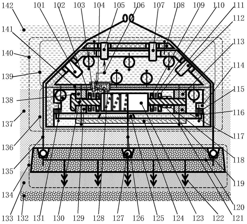
[0044] Embodiment 1: as figure 1 As shown, a floating seabed foundation includes a seabed foundation box 140, a release cable 126, and a gravity anchor 134. The seabed foundation box 140 is connected to the gravity anchor 134 through the release cable 126, separated The board 141 divides the seabed base box 140 into an upper box 139 and a lower box 136, the upper box 139 is fixedly installed with an underwater acoustic communication machine 105 and a release device 128, and the signal cable 106 is connected to the water Acoustic communicator 105 and the release device 128, the release device 128 is connected to the partition 141 using connecting bolts 508, and various self-contained observation instruments such as ADCP 107 and CTD 101 can be carried inside the seabed base box , and other optional observation instruments 112, such as OBS (undersea seismograph), suspended sediment collector; fixedly installed with a cable winding device in the lower box 136, the cable winding de...
Embodiment 2
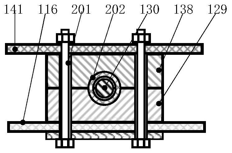
[0050] Embodiment 2, embodiment 2 is to further limit embodiment 1; the release device 128 includes a bolt 501, a release device frame 502, an electromagnet 503, a signal cable 106, a ferromagnetic disc 504, a connecting rod 505, Corrosion-resistant spring 506, release cable 126, slider 507 and connecting bolt 508; the electromagnet 503 is fixed on the frame 502 of the release device using the bolt 501, and the connecting rod 505 is covered with the corrosion-resistant spring 506, the right end is threaded to the slider 507, passing through the hole on the frame 502, the left end is threaded to the ferromagnetic disc 504, and the ferromagnetic disc 504 is installed on the right side of the electromagnet 503, The release cable 126 is sleeved on the slider 507 . A felt pad 509 is arranged between the release device frame 502 and the partition 141, and the connecting bolt 508 connects the release device frame 502, the partition 141 and the felt pad 509 as one; the underwater acou...
Embodiment 3
[0051] Embodiment 3. Embodiment 3 is to further limit Embodiment 1 or 2; the gravity anchor 134 includes a reinforced concrete block 120 and a barb 122, and the barb 122 is welded with the steel bar in the reinforced concrete block 120 as a whole. The barb 122 is welded under the reinforced concrete block 120; the steel bar and the barb 122 are made of corrosion-resistant stainless steel; the barb 122 is inserted into the soft and hard transitional sediment layer 133 to prevent the seabed foundation from sliding on the seabed under force, and the gravity anchor A suspension ring 127 is arranged at the center of 134 , and the release cable 126 is fixedly connected to the suspension ring 127 . The deployment cable 135 is attached to unmarked lifting eyes on both sides.
PUM
 Abstract
Description
Claims
Application Information