
Transformer oil temperature fiber grating monitoring system

A technology of fiber grating and transformer oil, which is applied to thermometers, instruments, thermometers, etc., which are subject to physical/chemical changes, can solve the problems of being susceptible to interference from the surrounding environment and electromagnetic fields, aggravated heat accumulation, and poor heat dissipation effect, and achieves measurement accuracy. And the effect of high effectiveness, simple and clear system operation, easy to expand and upgrade

Pending Publication Date: 2021-02-05
STATE GRID HENAN ELECTRIC POWER COMPANY ANYANG POWER SUPPLY
View PDF0 Cites 0 Cited by
  • Summary
  • Abstract
  • Description
  • Claims
  • Application Information

AI Technical Summary

Problems solved by technology

[0002] The power transformer is a high-voltage electrical equipment for power transmission and transformation in the power system. It is responsible for the conversion of voltage and current and power transmission. Its performance directly affects the safe and stable operation of the power system. Since the transformer adopts a closed structure, The heat dissipation effect is poor, the heat accumulation is large, and the long-term high voltage, high current and full load operation state directly lead to heat accumulation, temperature rise, and transformer failure; therefore, it is necessary to monitor the oil temperature of the power transformer online to prevent the transformer from Overheating to ensure the safe operation of the transformer and prolong the life of its equipment; the traditional monitoring method of transformer winding temperature is electrical signal measurement and infrared measurement, temperature measurement system based on electrical signal such as thermocouple, resistance thermometer, etc., the sensor of this kind of electrical signal is easy Interferenced by electromagnetic fields, the measurement effect is not good; infrared temperature measurement is actually a non-contact temperature measurement. Although this method has high sensitivity and accuracy, it is easily disturbed by the surrounding environment and electromagnetic fields, and requires manual operation. Realize unmanned online monitoring. In addition, the infrared thermometer cannot be installed inside the transformer, and can only measure the temperature on the surface of the transformer. The error is relatively large. Therefore, a transformer oil temperature optical fiber that can realize large-scale remote real-time monitoring of transformer oil temperature is provided. Grating monitoring system is necessary

Method used


Image

  • Transformer oil temperature fiber grating monitoring system
  • Transformer oil temperature fiber grating monitoring system
  • Transformer oil temperature fiber grating monitoring system

Examples


Embodiment 1

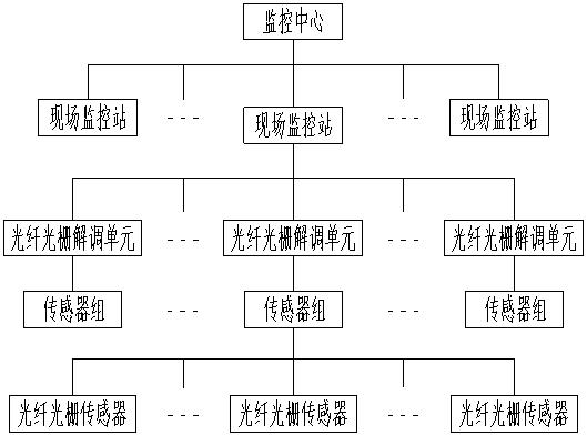
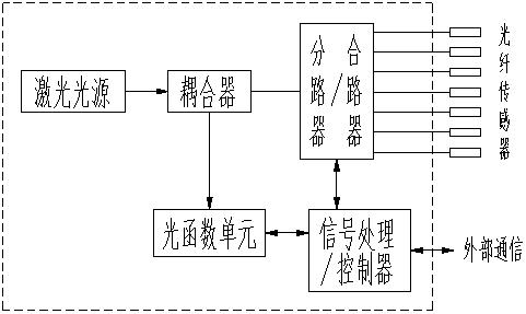
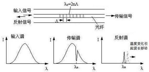
[0018] like Figure 1-3 As shown, the transformer oil temperature fiber optic grating monitoring system includes a fiber optic grating sensor, and the fiber optic grating sensor is arranged in the transformer oil tank and outside the transformer equipment, and is used to collect the temperature inside the transformer equipment oil tank and outside the transformer equipment. Fiber Bragg grating sensors form a sensor group, and the transformer oil temperature fiber Bragg grating monitoring system includes a plurality of sensor groups, and the sensor group is connected to a fiber Bragg grating demodulation unit through an optical fiber, and a plurality of fiber Bragg grating demodulation units are connected to The on-site monitoring station in this area is connected, and the transformer oil temperature fiber grating monitoring system includes a plurality of on-site monitoring stations, and a plurality of on-site monitoring stations are connected to the monitoring center through op...

Embodiment 2

[0021] like Figure 1-3 As shown, the transformer oil temperature fiber optic grating monitoring system includes a fiber optic grating sensor, and the fiber optic grating sensor is arranged in the transformer oil tank and outside the transformer equipment, and is used to collect the temperature inside the transformer equipment oil tank and outside the transformer equipment. Fiber Bragg grating sensors form a sensor group, and the transformer oil temperature fiber Bragg grating monitoring system includes a plurality of sensor groups, and the sensor group is connected to a fiber Bragg grating demodulation unit through an optical fiber, and a plurality of fiber Bragg grating demodulation units are connected to The on-site monitoring station in this area is connected, and the transformer oil temperature fiber grating monitoring system includes a plurality of on-site monitoring stations, and a plurality of on-site monitoring stations are connected to the monitoring center through op...


PUM


Abstract

The invention belongs to the technical field of transformer oil temperature monitoring, and particularly relates to a transformer oil temperature fiber grating monitoring system. The system comprisesfiber bragg grating sensors, the fiber bragg grating sensors are arranged in a transformer oil tank and outside transformer equipment, a plurality of fiber bragg grating sensors form a sensor group, the sensor group is connected with a fiber bragg grating demodulation unit through optical fibers, and the plurality of fiber bragg grating demodulation units are connected with an on-site monitoring station in the area. The plurality of on-site monitoring stations are connected with the monitoring center through optical fibers. The fiber bragg grating demodulation unit comprises a laser light source, the laser light source is connected with a coupler, the coupler is connected with a shunt / combiner unit and an optical function unit, the shunt / combiner unit is connected with a fiber bragg grating sensor, the optical function unit is connected with a signal processing / controller unit, and the signal processing / controller unit is connected with a field monitoring station. The system is reasonable in structure, convenient to expand and upgrade and capable of achieving large-range remote real-time monitoring of the transformer oil temperature.

Description

technical field [0001] The invention belongs to the technical field of transformer oil temperature monitoring, and in particular relates to a transformer oil temperature optical fiber grating monitoring system. Background technique [0002] The power transformer is a high-voltage electrical equipment for power transmission and transformation in the power system. It is responsible for the conversion of voltage and current and power transmission. Its performance directly affects the safe and stable operation of the power system. Since the transformer adopts a closed structure, The heat dissipation effect is poor, the heat accumulation is large, and the long-term high voltage, high current and full load operation state directly lead to heat accumulation, temperature rise, and transformer failure; therefore, it is necessary to monitor the oil temperature of the power transformer online to prevent the transformer from Overheating to ensure the safe operation of the transformer an...

Claims


Application Information

Patent Timeline
Patent Type & Authority Applications(China)
IPC IPC(8): G01K1/024G01K1/02G01K11/32
CPCG01K1/02G01K1/024G01K11/32
Inventor 张占营陈阳魏民张霄冯晓兰席晟哲呼建礼彭超郭俊杰李昕洁胡明迪孙浩然崔哲芳赵新航赵叶茹王远赵悠悠
Owner STATE GRID HENAN ELECTRIC POWER COMPANY ANYANG POWER SUPPLY
Learn More