Garbage pyrolysis and purification treatment equipment

A purification treatment and pyrolysis technology, applied in grain treatment, chemical instruments and methods, special forms of dry distillation, etc., can solve the problems of mixing, heat loss, and high manufacturing costs, meet production needs, prevent agglomeration, and separate efficiency. high effect

Pending Publication Date: 2021-02-09
中海国弘能源科技有限公司
View PDF0 Cites 3 Cited by
  • Summary
  • Abstract
  • Description
  • Claims
  • Application Information

AI Technical Summary

Problems solved by technology

[0003] At present, there are many devices for waste pyrolysis treatment on the market, and there are still some defects or areas that need to be improved in the waste heat treatment devices. Our company has found the following technical problems to be solved: 1. Domestic waste is often mixed with a large amount of Waste liquid and waste water, such waste liquid and waste water will greatly affect the subsequent pyrolysis treatment process in the subsequent pyrolysis treatment process, and in rainy or heavy rainfall seasons, it will also cause domestic waste to be unable to be completely pyrolyzed, resulting in A large amount of heat is lost, which is not conducive to the development of the company's waste pyrolysis treatment, and there is no solid-liquid separation device on the market to solve this problem, which cannot meet the progress of the company's large-scale domestic waste treatment; 2. If using Some conventional mechanical devices for filtrate separation operations have the problems of high manufacturing cost and low efficiency of separation of domestic waste and filtrate, and in the actual operation process, it is also necessary to consider that some waste filtrates are hidden in domestic waste, such as bottle-shaped The waste liquid in the container and shell-shaped container cannot be effectively separated; 3. The operation of separating domestic waste and filtrate needs to consider the realization of batch and continuous operation, and needs to meet the actual needs of the continuous treatment of large quantities of domestic waste; 4 , Our company will operate the solid-liquid separation of domestic waste. Domestic waste often contains a lot of iron impurities. During the processing of large quantities of domestic waste, these iron impurities can be recycled and reused to avoid waste of resources; 5. These iron impurities are often mixed in domestic waste irregularly, and cannot be pyrolyzed in the subsequent pyrolysis treatment process, and remain in the pyrolysis treatment device. After cooling, they will form lumps and adhere to the pyrolysis treatment device. 6. The carbides produced during the pyrolysis process of waste are easy to form lumps after condensation, occupying a large amount of space inside the pyrolysis treatment device of waste, and are easy to block the waste slag discharge Export, which brings great troubles to the large-scale waste pyrolysis treatment operation of enterprises

Method used


Image

  • Garbage pyrolysis and purification treatment equipment
  • Garbage pyrolysis and purification treatment equipment
  • Garbage pyrolysis and purification treatment equipment

Examples


Embodiment Construction

[0030] In order to enable those skilled in the art to better understand the technical solution of the present invention, the present invention will be described in detail below in conjunction with the accompanying drawings. The description in this part is only exemplary and explanatory, and should not have any limiting effect on the protection scope of the present invention. .

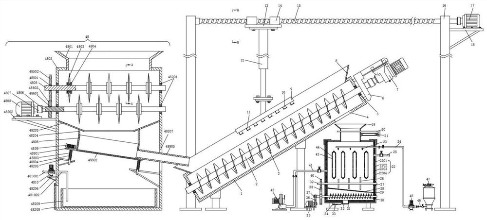
[0031] Such as Figure 1-Figure 10 As shown, the specific structure of the present invention is: a kind of waste pyrolysis purification treatment equipment, including a wall assembly 22 and a feeding cylinder 19, and the wall assembly 22 includes an outer isolation layer 2201, a thermal insulation cotton layer 2203 and a refractory layer 2204 , the outer insulation layer 2201 is welded by metal plates, the insulation cotton layer 2203 is fixed between the outer insulation layer 2201 and the refractory layer 2204 through the fixed pillar 2202 on the side wall of the outer insulation layer 2201, and the ...


PUM


Abstract

The invention discloses garbage pyrolysis and purification treatment equipment, and relates to the technical field of garbage pyrolysis and purification treatment. The garbage pyrolysis and purification treatment equipment comprises a wall body assembly and a feeding cylinder, wherein the wall body assembly comprises an outer isolation layer, a heat preservation cotton layer and a fireproof layer,the outer isolation layer is formed by welding metal plates, the heat preservation cotton layer is fixed between the outer isolation layer and the fireproof layer through fixing supporting columns onthe side wall of the outer isolation layer, the heat preservation cotton layer is in a bent folding structure shape, the fireproof layer is formed by stacking refractory bricks, a spray head and a waste gas oxidation chamber body are arranged inside the wall body assembly, a stirring rotating shaft is rotationally arranged below the waste gas oxidation chamber body, stirring rods are arranged onthe stirring rotating shaft at intervals, a partition plate body is obliquely arranged below the stirring rotating shaft, and a slag outlet groove is formed in the side part of the partition plate body. According to the garbage pyrolysis and purification treatment equipment, solid-liquid separation operation of household garbage can be realized, filtrate in the household garbage is prevented frombeing brought into subsequent processing operation, automatic lifting and feeding operation of the household garbage can be realized, the operation of removing iron impurities is realized, and waste residues after pyrolysis are prevented from being condensed into blocks.

Description

technical field [0001] The invention relates to the technical field of garbage pyrolysis purification treatment, in particular to equipment for garbage pyrolysis purification treatment. Background technique [0002] Garbage is solid waste generated in human daily life and production. Due to the large amount of discharge, complex and diverse components, and polluting, resourceful and social nature, it needs harmless, resourceful, reduction and socialized treatment. If not handled properly, it will pollute the environment, affect environmental sanitation, waste resources, destroy production and living safety, and disrupt social harmony. Garbage disposal is to quickly remove the rubbish, carry out harmless treatment, and finally make reasonable use of it. Nowadays, the widely used garbage disposal methods are sanitary landfill, high-temperature composting and incineration. The purpose of garbage disposal is harmless, resourceful and reduction. [0003] At present, there are m...

Claims


Application Information

Patent Timeline
Patent Type & Authority Applications(China)
IPC IPC(8): B02C18/14B02C18/18B02C18/24B02C23/08B09B3/00C10B53/00C10B57/00B01D33/03B03C1/30
CPCB02C18/0092B02C18/142B02C18/18B02C18/24B02C23/08C10B53/00C10B57/00B01D33/0346B03C1/30B02C2201/06B09B3/40
Inventor 贺世海刘安海刘良奇
Owner 中海国弘能源科技有限公司
Why Eureka
Try Eureka