High-thermal-conductivity isothermal body temperature control irradiation device

An irradiation device and high thermal conductivity technology, which is applied in the field of nuclear power materials, can solve the problems of limited irradiation space, low use cost, and low thermal conductivity, and achieve the effects of uniform temperature distribution, increased temperature, and simple structure

Pending Publication Date: 2021-02-23
INST OF NUCLEAR PHYSICS & CHEM CHINA ACADEMY OF
View PDF0 Cites 4 Cited by
  • Summary
  • Abstract
  • Description
  • Claims
  • Application Information

AI Technical Summary

Problems solved by technology

[0004] At present, there are mainly three kinds of devices that provide temperature loading for irradiated material samples in the reactor: the first is to establish a specific test loop in the reactor, place the material sample to be tested in the test loop, and then use the setting in the reactor to The fluid at high temperature is used to heat the nuclear power material to be tested, but due to the extremely high construction and operating costs of the test circuit in the reactor, and the limited irradiation space, this device is not suitable for most tests; the second is to use a belt The instrumented irradiation device for heating elements, which requires pipeline layout in the reactor, is extremely inconvenient, and is limited by the reliability factors of heaters and other devices under irradiation conditions, and the device cannot be widely used; the third The static irradiation device is used for temperature loading. The static irradiation device has a simple structure and low cost, and has been widely used in nuclear material irradiation assessment tests.
[0005] Existing static irradiation devices are mainly based on the principle that nuclear power materials themselves will generate heat in the nuclear radiation neutron field, using the inert gas gap as the nuclear material insulation layer, and adjusting the thickness of the inert gas gap or the composition of the inert gas (usually helium However, this method has the following defects: 1) Due to the small neutron absorption cross-section and nuclear heating rate of the nuclear power material irradiation sample itself, the radiation of some assessment test objects The irradiation temperature requirement is very high, and the target irradiation temperature cannot be reached only by relying on the self-heating of the material and the inert gas insulation layer; 2) For studying the microscopic changes such as creep, growth and hardening of nuclear power materials, it is necessary to control the temperature of nuclear power material samples at Fluctuates in a very small temperature range of about 10°C, and only uses an inert gas gap as the traditional static irradiation device for the insulation layer. Due to the low thermal conductivity of the sample itself, the nuclear heat distribution of the sample in the height direction is not uniform and the sample is exposed during the irradiation process. It is in direct contact with the normal temperature irradiation tank, and the temperature of the contact part is extremely low. These factors will lead to a large temperature difference between different parts of the sample, which seriously affects the evaluation of the radiation performance of nuclear power materials; 3) The sensitivity of nuclear power materials to the thickness of the air gap Extremely high, due to the shaking, vibration and other problems in the irradiation tank of the traditional static irradiation device, it is easy to change the position of the nuclear power material sample in the irradiation tank, resulting in inconsistent thickness of the gas insulation layer wrapped around the nuclear power material. which in turn leads to its own uneven temperature distribution

Method used


Image

  • High-thermal-conductivity isothermal body temperature control irradiation device
  • High-thermal-conductivity isothermal body temperature control irradiation device
  • High-thermal-conductivity isothermal body temperature control irradiation device

Examples


Embodiment 1

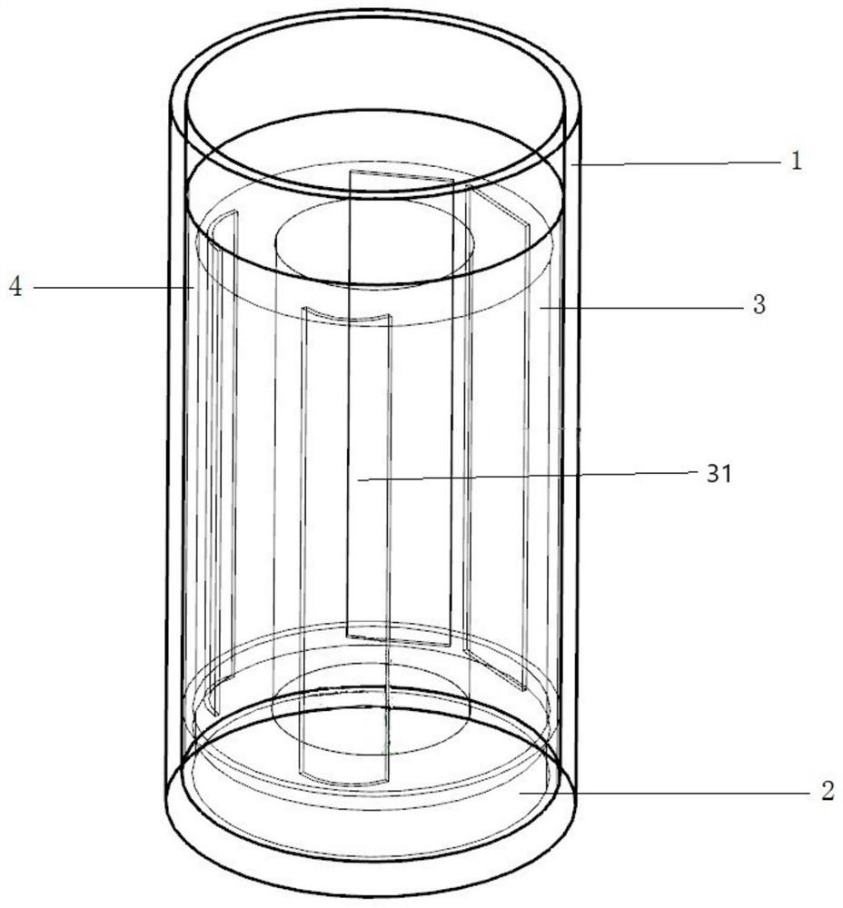
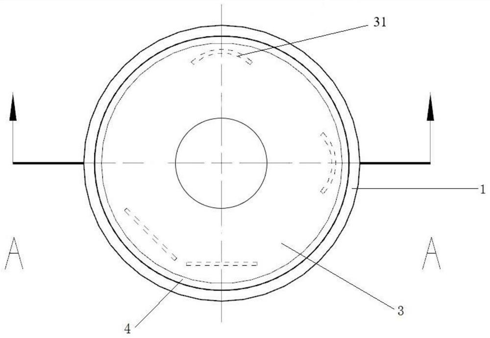
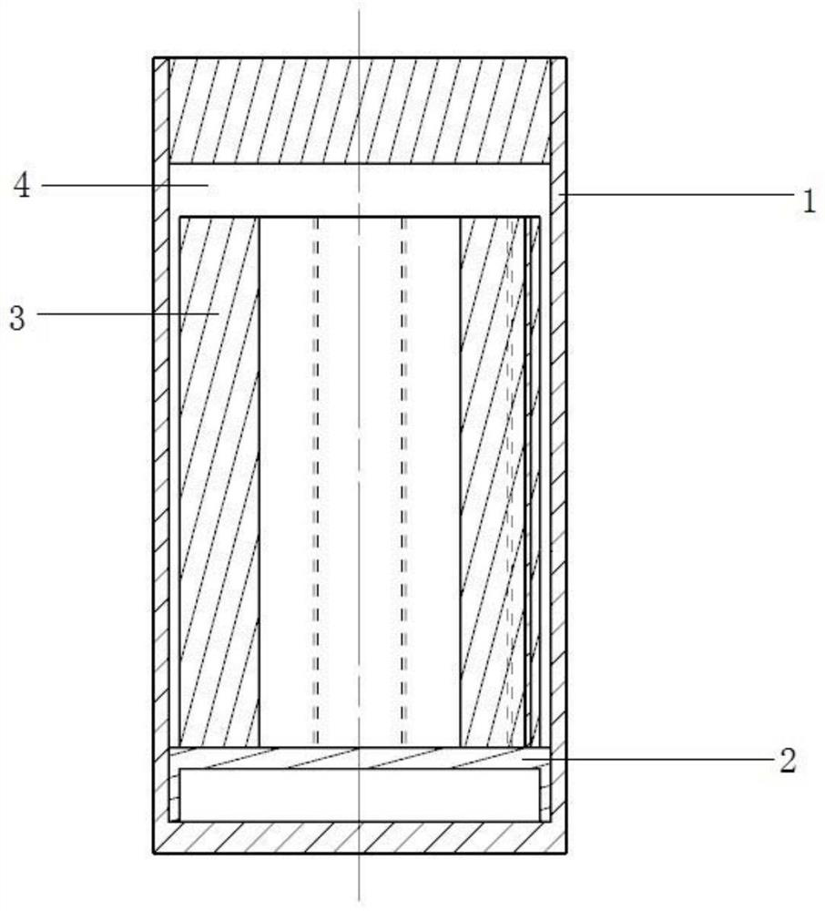
[0030] In this embodiment, the samples to be irradiated are two 1 / 4 arc thin zirconium alloy claddings and two zirconium alloy plates respectively, and the irradiation temperature required for the test is 350°C. The thickness of the side wall of the irradiation capsule is 1.5mm, the thickness of the bottom of the irradiation capsule is 5mm, the thickness of the top cover is 10mm, the inner diameter of the irradiation capsule is 36mm, and the outer diameter is 39mm. The capsule is made of nuclear grade 6061 aluminum material. A pure copper circular isothermal body with an outer diameter of 33.4 mm and an inner diameter of 21 mm is placed inside the irradiation capsule. By adjusting the inner and outer diameters of the isothermal body, the calorific value of the pure copper isothermal body is adjusted to make the sample reach the target irradiation temperature. The lower end of the pure copper ring-shaped isothermal body is cushioned with a zirconia ceramic material block with a...


PUM


Abstract

The invention discloses a high-conductivity isothermal body temperature control irradiation device. The device comprises an irradiation capsule, a cushion block, an isothermal body and an inert gas layer. The irradiation capsule is an outer protective shell of the irradiation device and provides support for each component and a to-be-irradiated sample; the isothermal body provides temperature compensation for the to-be-measured sample by utilizing the nuclear irradiation heating characteristic of the isothermal body, so that the to-be-measured sample is in a uniform and stable temperature environment; the inert gas layer is arranged in a gap between the inner surface of the irradiation capsule shell and the outer surface of the isothermal body so as to perform heat preservation; the cushion block is arranged between the contact surfaces of the isothermal body and the irradiation capsule so as to perform heat insulation. The irradiation device disclosed by the invention provides a uniform and stable irradiation temperature environment for irradiation examination of a nuclear power material, is simple and reliable in structure and low in cost, and provides support for a reliable nuclear power material irradiation test.

Description

technical field [0001] The invention belongs to the field of nuclear power materials, in particular to a high-conductivity isothermal body temperature control irradiation device. Background technique [0002] Energy is the cornerstone of social and economic development. Vigorously developing clean energy is of great significance to the harmonious development of man and nature. Nuclear energy is clean, safe and efficient, and has become an important direction for countries to develop clean energy. Nuclear power materials are the key factors supporting the development of nuclear power plants such as large-scale advanced pressurized water reactors and high-temperature gas-cooled reactors. However, nuclear power materials are also one of the bottlenecks currently restricting the development of nuclear power technology. With the deepening of my country's nuclear power autonomy, it is urgent to study the impact of nuclear radiation on nuclear power materials. [0003] The radiati...

Claims


Application Information

Patent Timeline
Patent Type & Authority Applications(China)
IPC IPC(8): G01N1/44
CPCG01N1/44
Inventor 王梓郭斯茂米向秒王冠博唐彬钱达志刘耀光周韦袁姝张松宝
Owner INST OF NUCLEAR PHYSICS & CHEM CHINA ACADEMY OF
Why Eureka
Try Eureka