Method for modifying detected camshaft position, controller, internal combustion engine and vehicle
A camshaft, internal combustion engine technology, applied in the field of vehicles with such an internal combustion engine, can solve problems such as difficulty in evaluating compensation accuracy, and achieve the effect of simplifying the method
- Summary
- Abstract
- Description
- Claims
- Application Information
AI Technical Summary
Problems solved by technology
Method used
Image
Examples
Embodiment Construction
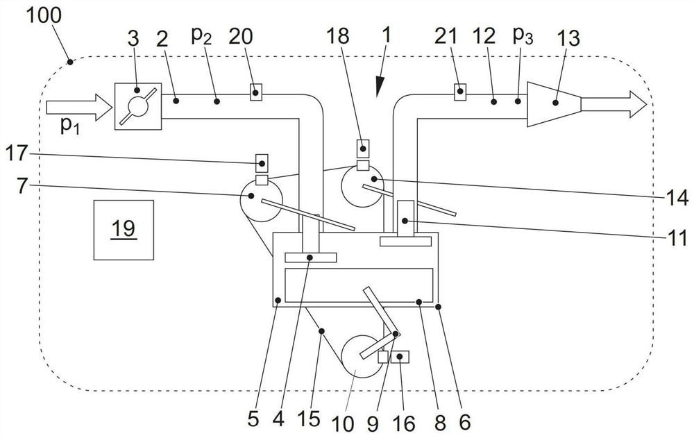
[0063] figure 1 Shows a schematic diagram of a vehicle 100 with an internal combustion engine 1 having the following features: Fresh air or fresh gas is fed into the combustion chamber 5 of a cylinder 6 via an intake manifold 2 between a throttle valve 3 and a The intake valves extend between 4. The movement of the intake valve 4 is controlled by an adjustable intake camshaft 7 . In the cylinder 6 or in the intake manifold 2 , the supplied fresh air is mixed with fuel which is combusted in the cylinder and which now drives the piston 8 . The piston movement is transmitted via the crank 9 to the crankshaft 10, the rotation of which is used to drive the vehicle 100 through a drive train not shown.
[0064] After combustion, the piston 8 expels the exhaust gas from the combustion chamber 5 through the exhaust valve 11 into the exhaust manifold 12 and on to the turbine 13 of the exhaust gas turbocharger, which may optionally be equipped with Wastegate or adjustable turbo geomet...
PUM
 Abstract
Description
Claims
Application Information
 - R&D
- Intellectual Property
- Life Sciences
- Materials
- Tech Scout
- Unparalleled Data Quality
- Higher Quality Content
- 60% Fewer Hallucinations
Browse by: Latest US Patents, China's latest patents, Technical Efficacy Thesaurus, Application Domain, Technology Topic, Popular Technical Reports.
© 2025 PatSnap. All rights reserved.Legal|Privacy policy|Modern Slavery Act Transparency Statement|Sitemap|About US| Contact US: help@patsnap.com


