Unlock instant, AI-driven research and patent intelligence for your innovation.

New energy automobile damping device

A technology for new energy vehicles and shock absorbers, applied in injection devices, liquid injection devices, springs/shock absorbers, etc. Guaranteed effect, reduced shock absorption effect, reduced service life effect

Inactive Publication Date: 2021-03-09
刘思琪
View PDF0 Cites 0 Cited by
  • Summary
  • Abstract
  • Description
  • Claims
  • Application Information

AI Technical Summary

Problems solved by technology

[0004] The purpose of the present invention is to solve the problem that the automobile shock absorber in the prior art is easy to be contaminated with soil during driving. If the soil is not cleaned for a long time, the shock absorption effect will be poor, and the shock absorber will be worn and rusted during use. Will affect the service life, and proposed a new energy vehicle shock absorber

Method used


Image

  • New energy automobile damping device
  • New energy automobile damping device
  • New energy automobile damping device

Examples


Embodiment 1

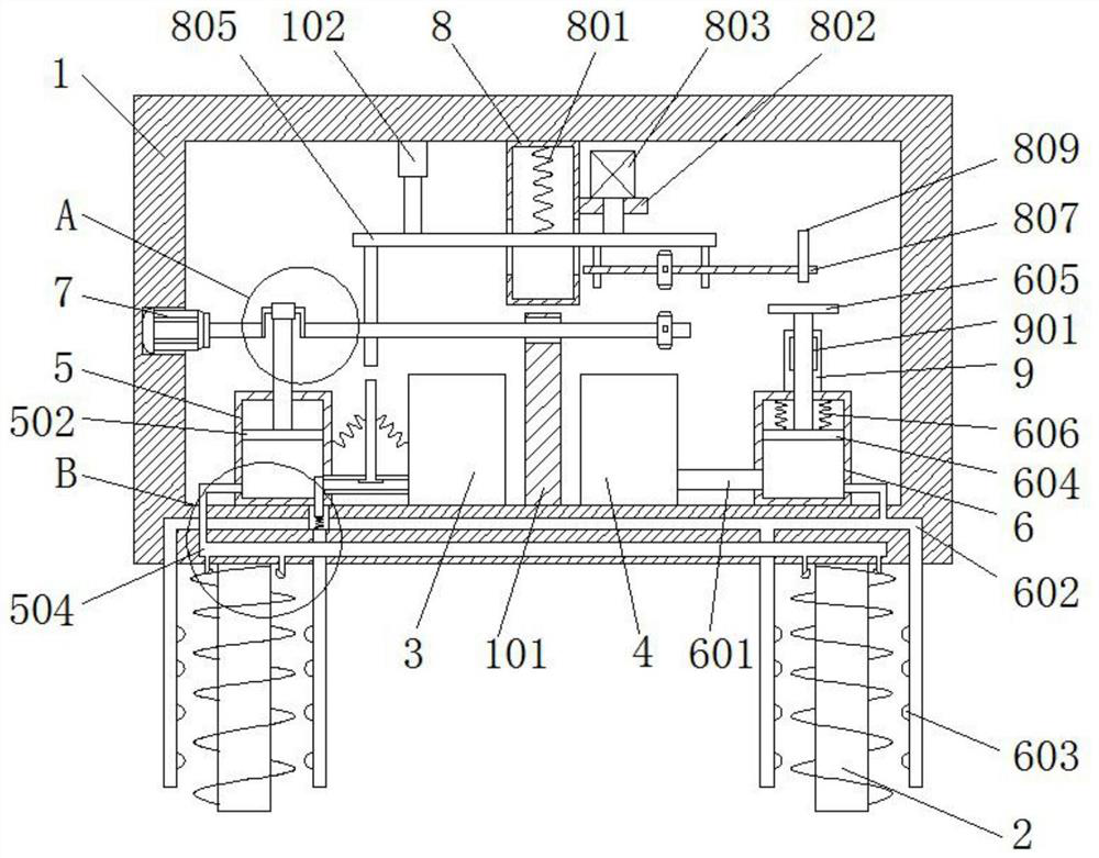
[0032] refer to Figure 1-7 , a new energy vehicle shock absorber, comprising a shock absorber 2, the top of the shock absorber 2 is fixedly connected with a box body 1, and the box body 1 is fixedly connected with a water tank 3 and an anti-rust oil tank 4, and the box body 1 is provided with The water intake mechanism and the oil intake mechanism, the first connection pipe 503 is connected between the water intake mechanism and the water tank 3, the second connection pipe 601 is connected between the oil intake mechanism and the anti-rust oil tank 4, and the inner wall of the box body 1 is provided with a placement groove, A motor 7 is fixedly connected to the placement slot, and the output end of the motor 7 is connected to a first rotating shaft 701 in rotation. A crankshaft 702 is fixedly connected to the first rotating shaft 701. The outer wall of the crankshaft 702 is sleeved with a sliding sleeve 703. The bottom of the sliding sleeve 703 is connected to the The water i...

Embodiment 2

[0039] refer to figure 1 , figure 2 , Figure 5 with Image 6 , a new energy vehicle shock absorber, comprising a shock absorber 2, the top of the shock absorber 2 is fixedly connected with a box body 1, and the box body 1 is fixedly connected with a water tank 3 and an anti-rust oil tank 4, and the box body 1 is provided with The water intake mechanism and the oil intake mechanism, the first connection pipe 503 is connected between the water intake mechanism and the water tank 3, the second connection pipe 601 is connected between the oil intake mechanism and the anti-rust oil tank 4, and the inner wall of the box body 1 is provided with a placement groove, A motor 7 is fixedly connected to the placement slot, and the output end of the motor 7 is connected to a first rotating shaft 701 in rotation. A crankshaft 702 is fixedly connected to the first rotating shaft 701. The outer wall of the crankshaft 702 is sleeved with a sliding sleeve 703. The bottom of the sliding sleev...

Embodiment 3

[0047] refer to figure 1 , Figure 5 with Image 6 , a new energy vehicle shock absorber, comprising a shock absorber 2, the top of the shock absorber 2 is fixedly connected with a box body 1, and the box body 1 is fixedly connected with a water tank 3 and an anti-rust oil tank 4, and the box body 1 is provided with The water intake mechanism and the oil intake mechanism, the first connection pipe 503 is connected between the water intake mechanism and the water tank 3, the second connection pipe 601 is connected between the oil intake mechanism and the anti-rust oil tank 4, and the inner wall of the box body 1 is provided with a placement groove, A motor 7 is fixedly connected to the placement slot, and the output end of the motor 7 is connected to a first rotating shaft 701 in rotation. A crankshaft 702 is fixedly connected to the first rotating shaft 701. The outer wall of the crankshaft 702 is sleeved with a sliding sleeve 703. The bottom of the sliding sleeve 703 is conn...


PUM


Abstract

The invention discloses a new energy automobile damping device, and belongs to the technical field of automobile damping. The new energy automobile damping device comprises a damper, a box body is fixedly connected to the top of the damper, a water tank and an anti-rust oil tank are fixedly connected in the box body, a water taking mechanism and an oil taking mechanism are arranged in the box body, a first connecting pipe is connected between the water taking mechanism and the water tank, a second connecting pipe is connected between the oil taking mechanism and the anti-rust oil tank, a containing groove is formed in the inner wall of the box body, a motor is fixedly connected in the containing groove, the output end of the motor is rotationally connected with a first rotating shaft, a crankshaft is fixedly connected to the first rotating shaft, the outer wall of the crankshaft is sleeved with a sliding sleeve, and the bottom of the sliding sleeve is connected with the water taking mechanism. The damper can be cleaned and oiled, and the problems that the damper is blocked and affected by soil, and the damping effect is poor due to rusting are solved.

Description

technical field [0001] The invention relates to the technical field of automobile shock absorption, in particular to a new energy automobile shock absorption device. Background technique [0002] New energy vehicles refer to the use of unconventional vehicle fuels as the power source, or the use of conventional vehicle fuels, the adoption of new vehicle power devices, and the comprehensive vehicle power control and advanced technology in driving, forming advanced technical principles and new features. Technology, new structure vehicles, new energy vehicles include four types of hybrid electric vehicles, pure electric vehicles, fuel cell electric vehicles, other new energy, such as super capacitors, flywheels and other high-efficiency energy storage vehicles, etc., unconventional vehicles Fuel refers to fuels other than gasoline, diesel, natural gas, liquefied petroleum gas, ethanol gasoline, methanol, and dimethyl ether. With the rapid development of the automobile industry,...

Claims


Application Information

Patent Timeline
Patent Type & Authority Applications(China)
IPC IPC(8): F16F3/04B08B3/02B08B13/00B05B7/24
CPCB05B7/2486B08B3/02B08B13/00F16F3/04F16F2230/10
Inventor 刘思琪
Owner 刘思琪