Eureka AIR delivers breakthrough ideas for toughest innovation challenges, trusted by R&D personnel around the world.

Microgrid structure based on fuel cell and operation control method

A fuel cell and operation control technology, applied in battery overcharge protection, battery circuit device, battery overdischarge protection, etc. problems, to achieve the effect of realizing over-discharge protection, achieving balance, and simplifying the structure of the micro-grid

Active Publication Date: 2021-03-12
SICHUAN ENERGY INTERNET RES INST TSINGHUA UNIV
View PDF13 Cites 0 Cited by
  • Summary
  • Abstract
  • Description
  • Claims
  • Application Information

AI Technical Summary

Problems solved by technology

[0004] However, there are certain defects in the above-mentioned scheme, for example, the problem of battery over-discharging is easy to occur when the generated electric energy is not enough.
Moreover, the current micro-grid has not realized the overcharge and over-discharge protection of the battery from the aspect of energy scheduling, and cannot control the operation of each power generation unit according to the conditions of the battery and the load. imbalance problem

Method used


Image

  • Microgrid structure based on fuel cell and operation control method
  • Microgrid structure based on fuel cell and operation control method
  • Microgrid structure based on fuel cell and operation control method

Examples


Embodiment Construction

[0031] The present invention will be described in further detail below in conjunction with the accompanying drawings and specific embodiments.

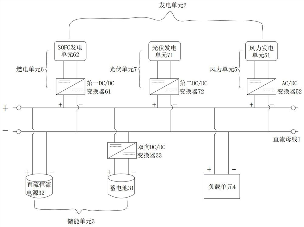
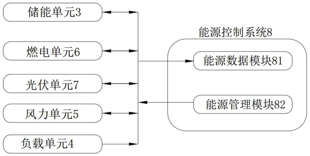
[0032] This embodiment discloses a fuel cell-based microgrid structure and operation control method, such as figure 1 and figure 2 As shown, the microgrid structure includes a power generation unit 2, an energy storage unit 3, and a load unit 4 respectively connected to the DC bus 1, the power generation unit 2 includes a combustion unit 6 and a photovoltaic unit 7, and the energy storage unit 3 includes The storage battery 31 and the DC constant current power supply 32 of 1, the power generation unit 2, the energy storage unit 3 and the load unit 4 are all connected to the energy control system 8 to send operation data to the energy control system 8 and receive energy management scheduling of the energy control system 8;

[0033] The energy control system 8 includes an energy data module 81 for collecting operating data of the powe...


PUM


Abstract

The invention provides a microgrid structure based on a fuel cell and an operation control method, and the microgrid structure comprises the steps: A, enabling a storage battery SoC to be greater thana first set value and less than a second set value, and starting the storage battery to discharge when the power needed by a load unit is greater than the total power of a power generation unit; whenthe power required by the load unit is smaller than the total power of the power generation unit, starting the storage battery for charging; B, when the SoC of the storage battery is greater than a second set value, cutting off part or all of the power generation units from the microgrid, starting the storage battery to discharge, and completely connecting the power generation units to the microgrid until the SoC of the storage battery is less than a third set value; C, when the SoC of the storage battery is smaller than a first set value, connecting the direct-current constant-current powersupply to the microgrid until the power required by the load unit is smaller than that of the power generation unit. According to the scheme, charging and discharging of the storage battery can be controlled according to conditions, the power generation units are controlled to be input into or disconnected from the micro-grid, the direct-current constant-current power supply is controlled to be connected into or disconnected from the micro-grid, and over-charging and over-discharging protection of the storage battery is achieved while supply and demand power balance is achieved.

Description

technical field [0001] The invention belongs to the technical field of microgrid electric energy management, and in particular relates to a fuel cell-based microgrid structure and an operation control method. Background technique [0002] Microgrid, also called microgrid, refers to a small power generation and distribution system composed of distributed power sources, energy storage devices, energy conversion devices, loads, monitoring and protection devices, etc. [0003] With the maturity of fuel power generation technology, fuel cell power generation is gradually introduced into the microgrid. As a new type of green energy, fuel cells can use liquid fuels such as methanol and ammonia water. They have the characteristics of high energy density, high conversion efficiency, stability and no noise. Using fuel cells as a supplementary power source, they are combined with photovoltaics and batteries to form a "photovoltaic -Battery-fuel cell" "solar-storage-combustion" complem...

Claims


Application Information

Patent Timeline
Patent Type & Authority Applications(China)
IPC IPC(8): H02J3/38H02J3/32H02J7/00
CPCH02J3/381H02J3/32H02J7/00302H02J7/00306H02J2300/24H02J2300/28H02J2300/30Y02E10/56
Inventor 曾庆谢重阳林今连利波胡强高丹慧
Owner SICHUAN ENERGY INTERNET RES INST TSINGHUA UNIV
Why Eureka
Eureka Blog
Learn More