Method for producing a porous transport layer for an electrochemical cell

An electrochemical and transport layer technology, applied in electrochemical generators, components of fuel cells, fuel cells, etc., can solve the problems of complex and expensive technology, and achieve the effect of less consumption of metal materials and cost-effective

Pending Publication Date: 2021-03-16
HOELLER ELECTROLYZER GMBH
View PDF5 Cites 0 Cited by
  • Summary
  • Abstract
  • Description
  • Claims
  • Application Information

AI Technical Summary

Problems solved by technology

Plasma spraying under vacuum is technically complex and expensive and leads to different layer thicknesses in the plane

Method used


Image

  • Method for producing a porous transport layer for an electrochemical cell
  • Method for producing a porous transport layer for an electrochemical cell
  • Method for producing a porous transport layer for an electrochemical cell

Examples


Embodiment Construction

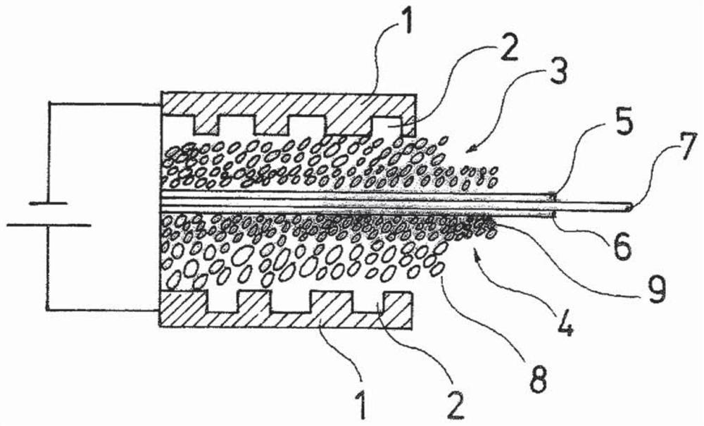
[0037] figure 1 The basic structure of a PEM electrolyzer is shown. The voltage for the generation of hydrogen and oxygen from water is applied to the two outer bipolar plates 1 , which have channels 2 for the supply of reactants, water, and for the removal of the reaction products hydrogen and oxygen. The channels 2 of the bipolar plate 1 opening towards the interior of the electrolyzer are covered by porous transport layers 3 , 4 which are electrically conductive and fluid-permeable. The porous transport layers 3 , 4 each contact in an electrically conductive manner on the catalyst layer 5 or 6 applied to the PEM 7 . In the electrolyzer shown here, for the generation of hydrogen and oxygen from water, there is a transport layer 4 of titanium on the anode side and a transport layer 3 of graphite on the cathode side. The catalyst layer 6 on the anode side is made of iridium oxide, and the catalyst layer 5 on the cathode side is made of platinum. Such a structure belongs to ...


PUM


Abstract

The invention relates to a method for producing a porous transport layer (4) for an electrochemical cell, said method consisting of mixing a metal powder with a binder and subsequently forming same into a foil. The foil is laid on a porous metal layer (8), the binder is then removed, and the remaining brown sublayer (9) is sintered to the porous metal layer (8), producing a porous transport layer(4) which has a porous metal layer (8) with a microporous metal layer (9) applied thereon.

Description

technical field [0001] The invention relates to a method for the manufacture of porous transport layers of electrochemical cells, in particular electrolyzers of the PEM type, in particular for the electrolysis of water into oxygen and hydrogen. Background technique [0002] Porous transport layer is also called PTL layer (Porous Transport Layer), used in electrochemical cells, such as PEM (Proton Exchange Membrane (proton exchange membrane) and Polymer Elektrolyt M embran (Polymer Electrolyte Membrane) type electrolyzers are used on the one hand to transport the reactants (eg water) to the catalyst and to the PEM of the cell stack formed by the electrolyser and on the other hand to remove the reaction products again. Furthermore, the porous transport layer also has an essential electrical function in order to conduct as large a current as possible over a large area to the catalyst on the cell membrane, or to conduct current away from the membrane, for example in the case of ...

Claims


Application Information

Patent Timeline
IPC IPC(8): C25B9/23C25B9/65C25B11/031C23C24/08H01M8/0245
CPCC23C24/087C25B9/65C25B9/23H01M8/0232H01M8/186H01M2008/1095H01M8/0202Y02E60/50Y02P70/50C25B11/032H01M8/0245
Inventor S·赫勒
Owner HOELLER ELECTROLYZER GMBH
Why Eureka
Try Eureka