An optical fiber sensing device based on ultrasonic detection voltage and its implementation method

A technology of optical fiber sensing and realization method, which is applied in measuring devices, measuring current/voltage, measuring electrical variables, etc., can solve the problems of being easily affected by the external environment, low sensitivity, low efficiency, etc. Influenced by external environmental factors, the effect of improving sensitivity and reducing attenuation

Active Publication Date: 2021-09-07
HARBIN UNIV OF SCI & TECH
View PDF26 Cites 0 Cited by
  • Summary
  • Abstract
  • Description
  • Claims
  • Application Information

AI Technical Summary

Problems solved by technology

[0004] Although the above-mentioned researchers use the method of applying voltage between the electrodes to make the diaphragm vibrate and radiate ultrasonic waves, or increase the thickness of the electrode sheet, reduce the capacitance loss, and increase the ultrasonic wave through the vibration of the diaphragm, or design a composite transducer, Compared with the traditional ultrasonic monitoring device, the measurement range, measurement accuracy and portability of the device have been greatly improved; the piezoelectric micromechanical ultrasonic transducer based on aluminum nitrate film proposed by Fu et al. only passes a single vibration element The transmitted ultrasonic pressure can only reach tens of pascals / volts, which is too small and requires many units to meet the emission requirements of ultrasonic devices
The sandwich-type composite transducer proposed by Hu et al. When the glued layer is in the case of large amplitude, it will be damaged in the stretching stage. Therefore, the sensitivity of the existing technology is not high, the efficiency is low, and it is easily affected by the external environment. and other problems, a fiber optic sensing device and implementation method for ultrasonic detection voltage with higher sensitivity, good stability and higher efficiency are proposed

Method used


Image

  • An optical fiber sensing device based on ultrasonic detection voltage and its implementation method
  • An optical fiber sensing device based on ultrasonic detection voltage and its implementation method
  • An optical fiber sensing device based on ultrasonic detection voltage and its implementation method

Examples


Embodiment Construction

[0035] The following embodiments will describe the specific implementation of an optical fiber sensing device based on ultrasonic detection voltage proposed by the present invention with reference to the accompanying drawings.

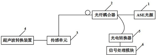
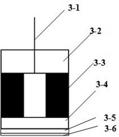
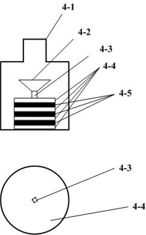
[0036] Such as figure 1 As shown, the present invention provides a structural diagram of an optical fiber sensing device based on ultrasonic detection voltage, the ASE light source (1) emits a light beam that is transmitted to the fiber coupler (2), and the output beam of the fiber coupler (2) is transmitted to the sensor Unit (3), the light beam is reflected and transmitted in the sensing unit (3), when the sensing unit (3) is placed in the ultrasonic conversion device (4), under the action of the ultrasonic conversion device (4), the sensing unit (3) The quartz diaphragm (3-4) is deformed, which changes the air-Pert cavity formed by the silicon ring (3-3), affects the optical path of the reflected light, and then produces light interference, and the ...


PUM

PropertyMeasurementUnit
thicknessaaaaaaaaaa
diameteraaaaaaaaaa
thicknessaaaaaaaaaa

Abstract

The patent of the present invention provides an optical fiber sensing device based on ultrasonic detection voltage, which includes an ASE light source, an optical fiber coupler, a sensing unit, an ultrasonic conversion device, a photoelectric converter, and a signal processing module. The patent of the invention conducts sensing through optical fiber, and utilizes the principle of the F-P cavity to make the light emitted by the ASE light source generate an interference spectrum in the F-P cavity. By detecting the interference spectrum, the voltage is measured, and the digital output is realized through the signal processing module. To achieve the purpose that can be displayed on the computer. The invention designs the structure of the ultrasonic energy transducing device, improves the efficiency, widens the frequency band of the ultrasonic wave, and realizes the purpose of monitoring the voltage. At the same time, it can be output on the host to realize the real-time monitoring of the voltage.

Description

technical field [0001] The invention belongs to the technical field of optical fiber sensing, and in particular relates to an optical fiber sensing device based on ultrasonic detection voltage. Background technique [0002] At present, the optical fiber sensing technology is gradually improving, and the monitoring device of optical fiber sensing is also becoming more and more perfect. Among them, in the optical fiber sensing device, the dielectric material and the structure of the sensing device will have a great impact on the optical fiber sensing. At present, there are many devices and methods for implementing ultrasonic detection by optical methods. [0003] Zhang Hui et al. (Zhang Hui, Li Zhi, Zheng Guanru et al; Design of air-coupled capacitive micro-ultrasonic transducer [J] Acoustica Sinica. 2019 No. 01. Pages 116-142) proposed an air-coupled capacitive micro-ultrasonic transducer The energy device method is to connect the DC bias voltage constant and the AC excitati...

Claims


Application Information

Patent Timeline
Patent Type & Authority Patents(China)
IPC IPC(8): G01R19/25G01R15/22
CPCG01R15/22G01R19/2503G01R19/2506
Inventor 冯月恭艾娜沈涛陈姣姣刘驰王振家王东兴黄海
Owner HARBIN UNIV OF SCI & TECH
Why Eureka
Try Eureka